i-ACTIVSENSE
i-ACTIVSENSE
i-ACTIVSENSE is a collective term covering a series of advanced safety and driver support systems which make use of a Forward Sensing Camera (FSC) and radar sensors. These systems consist of active safety and pre-crash safety systems.
These systems are designed to assist the driver in safer driving by reducing the load on the driver and helping to avert collisions or reduce their severity. However, because each system has its limitations, always drive carefully and do not rely solely on the systems.
Active Safety Technology
Active Safety Technology supports safer driving by helping the driver to recognise potential hazards and avert accidents.
Driver awareness support systems
Nighttime visibility
Left/right side and rear side detection
Road sign recognition
Inter-vehicle distance recognition
Driver fatigue detection
Rear obstruction detection when leaving a parking space
Full-surround recognition
Driver support systems
Inter-vehicle distance
Lane departure
Pre-Crash Safety Technology
Pre-crash safety technology is designed to assist the driver in averting collisions or reduce their severity in situations where they cannot be avoided.
Collision damage reduction in low vehicle speed range
Forward driving
Reverse driving
Collision damage reduction in medium/high speed range
Camera and Sensors
Forward Sensing Camera (FSC)
The Forward Sensing Camera (FSC) detects lane indications and recognises headlights, tail lights and city lights during nighttime driving. In addition, it also detects the vehicle ahead, pedestrians, or obstructions. The following systems also use the Forward Sensing Camera (FSC).
-
High Beam Control System (HBC)
-
Adaptive LED Headlights (ALH)
-
Driver Attention Alert (DAA)
-
Lane-keep Assist System (LAS) & Lane Departure Warning System (LDWS)
-
Traffic Sign Recognition System (TSR)
-
Advanced Smart City Brake Support (Advanced SCBS)
-
Smart Brake Support (SBS)
-
Mazda Radar Cruise Control with Stop & Go function (MRCC with Stop & Go function)
The Forward Sensing Camera (FSC) is installed at the top of the windscreen near the rearview mirror.
Refer to Forward Sensing Camera (FSC) (Search).
Radar sensor (front)
The radar sensor (front) functions by detecting the radio waves reflected off a vehicle ahead sent from the radar sensor. The following systems also use the radar sensor (front).
-
Mazda Radar Cruise Control with Stop & Go function (MRCC with Stop & Go function)
-
Distance Recognition Support System (DRSS)
-
Smart Brake Support (SBS)
The radar sensor (front) is mounted behind the radiator grille.
Refer to Radar Sensor (Front) (Search).
Radar sensors (rear)
The radar sensors (rear) function by detecting the radio waves reflected off a vehicle approaching from the rear or an obstruction sent from the radar sensors. The following systems also use the radar sensors (rear).
-
Blind Spot Monitoring (BSM)
-
Rear Cross Traffic Alert (RCTA)
The radar sensors (rear) are installed inside the rear bumper, one each on the left and right sides.
Refer to Radar Sensors (Rear) (Search).
Ultrasonic sensors (rear)
The ultrasonic sensors (rear) function by detecting the ultrasonic waves reflected off obstructions at the rear sent from the ultrasonic sensors. The following systems also use the ultrasonic sensors (rear).
-
Smart City Brake Support [Reverse] (SCBS R)
The ultrasonic sensors (rear) are mounted in the rear bumper.
Refer to Ultrasonic Sensors (Rear) (Search).
Front camera/side cameras/rear view camera
The front camera, side cameras, and rear camera shoot images of the area surrounding the vehicle. The 360° View Monitor uses each camera.
Cameras are installed to the front bumper, door mirrors, and liftgate.
Refer to Front Camera/Side Cameras/Rear Camera (Search).
High Beam Control System (HBC) (Some Models)
The HBC determines the conditions in front of the vehicle using the Forward Sensing Camera (FSC) while driving in darkness to automatically switch the headlights between high and low beams.
Refer to Forward Sensing Camera (FSC) (Search).
While driving the vehicle at a speed of about 30 km/h (19 mph) or more, the headlights are switched to high beams when there are no vehicles ahead or approaching in the opposite direction.
The system switches the headlights to low beams when one of the following occurs:
-
The system detects a vehicle or the headlights/lights of a vehicle approaching in the opposite direction.
-
The vehicle is driven on roads lined with streetlamps or on roads in well-lit cities and towns.
-
The vehicle is driven at less than about 20 km/h (12 mph).

The warning light turns on when the system has a malfunction.
Refer to Contact Authorised Mazda Repairer and Have Vehicle Inspected (Search).
-
Do not adjust the vehicle height, modify the headlight units, or remove the camera, otherwise the system will not operate normally.
-
Do not rely excessively on the HBC and drive the vehicle while paying sufficient attention to safety. Switch the headlights between the high beams and low beams manually if necessary.
The timing in which the system switches the headlights changes under the following conditions. If the system does not switch the headlights appropriately, manually switch between high and low beams according to the visibility as well as road and traffic conditions.
-
When there are sources of light in the area such as street lamps, illuminated signboards, and traffic signals.
-
When there are reflective objects in the surrounding area such as reflective plates and signs.
-
When visibility is reduced under rain, snow and foggy conditions.
-
When driving on roads with sharp turn or hilly terrain.
-
When the headlights/rear lamps of vehicles in front of you or in the opposite lane are dim or not illuminated.
-
When there is insufficient darkness such as at dawn or dusk.
-
When the luggage compartment is loaded with heavy objects or the rear passenger seats are occupied.
-
When visibility is reduced due to a vehicle in front of you spraying water from its tyres onto your windscreen.
To Operate the System
The HBC operates to switch the headlights automatically between high and low beams after the ignition is switched ON and the headlight switch is in the AUTO and high beam position.
The HBC determines that it is dark based on the brightness of the surrounding area. At the same time, the HBC indicator light (green) in the instrument cluster illuminates.

-
When the vehicle speed is about 30 km/h (19 mph) or more, the headlights automatically switch to high beams when there are no vehicles ahead or approaching in the opposite direction.
When the vehicle speed is less than about 20 km/h (12 mph), the HBC switches the headlights to low beams.
-
The low beams may not switch to high beams when cornering.
-
Operation of the HBC function can be disabled. Refer to Personalisation Features (Search).
Manual Switching
Switching to low beams
Shift the lever to the low beam position.
The HBC indicator light (green) turns off.
Switching to high beams
Turn the headlight switch to the position.
The HBC indicator light (green) turns off and the is illuminated.
Adaptive LED Headlights (ALH) (Some Models)
The ALH are a system which uses the Forward Sensing Camera (FSC) to determine the situation of a vehicle ahead or a vehicle approaching in the opposite direction while driving at night to automatically switch the illumination range of the headlights, the illuminated area, or the illumination brightness.
Refer to Forward Sensing Camera (FSC) (Search).
The ALH are controlled between high and low beams as follows to assure the driver’s visibility without dazzling a vehicle ahead or a vehicle approaching in the opposite direction.
Glare-Free High Beam
This feature dims only the high-beam light shone on the vehicle ahead.
The high beams will dim while driving at a speed of about 40 km/h (25 mph) or faster. When the vehicle speed is less than about 30 km/h (18 mph), the beams switch to the low beams.

Wide-Range Low Beam
This feature extends the illumination range of the light cast by the low beams while driving at a speed less than about 40 km/h (25 mph).

Highway Mode
This feature shifts the illumination angle of the light cast by the headlights upward while driving on highways.

The distance in which the ALH can detect objects varies depending on the surrounding conditions.
-
Do not modify the suspensions or headlight units, or remove the camera. Otherwise, the ALH may not operate normally.
-
Do not rely excessively on the ALH and drive the vehicle while paying sufficient attention to safety. Switch the headlights between the high beams and low beams manually if necessary.
Under the following conditions, the ALH may not operate normally. Manually switch between the high and low beams according to the visibility, and the road and traffic conditions.
-
When there are other sources of light in the area such as street lamps, illuminated signboards, and traffic signals.
-
When there are reflective objects in the surrounding area such as reflective plates and signs.
-
When visibility is reduced under rain, snow and foggy conditions.
-
When driving on roads with sharp curves or undulations.
-
When the headlights/rear lamps of vehicles ahead or in the opposite lane are dim or not illuminated.
-
When there is insufficient darkness such as at dawn or dusk.
-
When the luggage compartment is loaded with heavy objects or the rear passenger seats are occupied.
-
When visibility is reduced due to a vehicle ahead spraying water from its tyres onto your windscreen.
To Operate the System
The system switches the headlights to the high beams after the ignition is switched ON and the headlight switch is in the position. The ALH indicator light (green) in the instrument cluster turns on simultaneously.

The ALH determine that it is nighttime based on the brightness of the surrounding area.
The system cancels operation when the headlight switch is turned to a position other than , the headlights are manually switched to low beams, or the high beams are flashed on and off.
The system can be changed so that the ALH do not operate.
Refer to Personalisation Features (Search).
Manual Switching
Switching to low beams
Shift the lever to the low beam position.
The ALH indicator light (green) turns off.
Switching to high beams
Turn the headlight switch to the position.
The ALH indicator light (green) turns off and the is illuminated.
Blind Spot Monitoring (BSM)
The BSM is designed to assist the driver in checking the area to the rear of the vehicle on both sides during lane changes by notifying the driver of the presence of vehicles approaching from the rear in an adjacent lane.
The BSM detects vehicles approaching from the rear while travelling in the forward direction at a speed of 10 km/h (6.3 mph) or faster and notifies the driver by turning on the BSM warning indicator light and displaying the vehicle detection screen.
If the direction indicator lever is operated to signal a turn in the direction in which the BSM warning indicator light is illuminated while the approaching vehicle is detected, the BSM notifies the driver of possible danger by turning on the BSM warning indicator light, and by activating the warning sound and the warning screen indicator display.
The detection area on this system covers the driving lanes on both sides of the vehicle and from the rear part of the front doors to about 50 m (164 ft) behind the vehicle.

Always check the surrounding area visually before making an actual lane change:
The system is only designed to assist you in checking for vehicles at your rear when making a lane change. Due to certain limitations with the operation of this system, the BSM warning indicator light, the warning sound and the warning screen indicator display may not activate or they might be delayed even though a vehicle is in an adjacent driving lane. Always make it your responsibility as a driver to check the rear.
-
The BSM will operate when all of the following conditions are met:
-
The ignition is switched ON.
-
The BSM OFF indicator light in the instrument cluster is turned off.
-
The vehicle speed is about 10 km/h (6.3 mph) or faster.
-
-
The BSM will not operate under the following circumstances.
-
The vehicle speed falls below about 10 km/h (6.3 mph) even though the BSM OFF switch indicator light is turned off.
-
The selector lever is shifted to R position and the vehicle is reversing.
-
The turning radius is small (making a sharp turn, turning at intersections).
-
-
In the following cases, the BSM OFF indicator light turns on and operation of the system is stopped. If the BSM OFF indicator light remains illuminated, have the vehicle inspected at an Authorised Mazda Repairer as soon as possible.
-
Some problem with the system including the BSM warning indicator lights is detected.
-
A large deviation in the installation position of a radar sensor (rear) on the vehicle has occurred.
-
There is a large accumulation of snow or ice on the rear bumper near a radar sensor (rear). Remove any snow, ice or mud on the rear bumper.
-
Driving on snow-covered roads for long periods.
-
The temperature near the radar sensors (rear) becomes extremely hot due to driving for long periods on slopes during the summer.
-
The battery voltage has decreased.
-
-
Under the following conditions, the radar sensors (rear) cannot detect target objects or it may be difficult to detect them.
-
A vehicle is in the detection area at the rear in an adjacent driving lane but it does not approach. The BSM determines the condition based on radar detection data.
-
A vehicle is travelling alongside your vehicle at nearly the same speed for an extended period of time.
-
Vehicles approaching in the opposite direction.
-
A vehicle in an adjacent driving lane is attempting to pass your vehicle.
-
A vehicle is in an adjacent lane on a road with extremely wide driving lanes. The detection area of the radar sensors (rear) is set at the road width of expressways.
-
-
In the following case, the flashing of the BSM warning indicator light, and the activation of the warning sound and the warning screen indicator display may not occur or they may be delayed.
-
A vehicle makes a lane change from a driving lane 2 lanes over to an adjacent lane.
-
Driving on steep slopes.
-
Crossing the summit of a hill or mountain pass.
-
When there is a difference in the height between your driving lane and the adjacent lane.
-
Directly after the BSM system becomes operable by changing the setting.
-
-
If the road width is extremely narrow, vehicles 2 lanes over may be detected. The detection area of the radar sensors (rear) is set according to the road width of expressways.
-
The BSM warning indicator light may turn on and the vehicle detection screen may be displayed in the display in reaction to stationary objects (guardrails, tunnels, sidewalls, and parked vehicles) on the road or the roadside.
-
A BSM warning indicator light may flash or the warning beep and the warning screen indicator display may be activated several times when making a turn at a city intersection.
-
Turn off the BSM while pulling a trailer or while an accessory such as a bicycle carrier is installed to the rear of the vehicle. Otherwise, the radar’s radio waves will be blocked causing the system to not operate normally.
-
In the following cases, it may be difficult to view the illumination/flashing of the BSM warning indicator lights equipped on the door mirrors.
-
Snow or ice is adhering to the door mirrors.
-
The front door glass is fogged or covered in snow, frost or dirt.
-
-
The system switches to the Rear Cross Traffic Alert function when the selector lever is shifted to the reverse (R) position.
Refer to Rear Cross Traffic Alert (RCTA) (Search).
Blind Spot Monitoring (BSM) Warning Indicator Light/Display Indicator/Blind Spot Monitoring (BSM) Warning Beep
The BSM or Rear Cross Traffic Alert (RCTA) system notifies the driver of the presence of vehicles in adjacent lanes or at the rear of the vehicle using the BSM warning indicator light, the warning sound and the display indicator (BSM) while the systems are operational.
BSM warning indicator lights
The BSM warning indicator lights are equipped on the left and right door mirrors. The warning indicator lights turn on when a vehicle approaching from the rear in an adjacent lane is detected.

When the ignition is switched ON, the warning indicator light turns on momentarily and then turns off after a few seconds.
Forward driving (BSM operation)
The BSM detects vehicles approaching from the rear and turns on the BSM warning indicator lights equipped on the door mirrors according to the conditions. Additionally, while a BSM warning indicator light is illuminated, if the direction indicator lever is operated to signal a turn in the direction in which the BSM warning indicator light is illuminated, the BSM warning indicator light flashes.
Reverse driving (Rear Cross Traffic Alert (RCTA) system operation)
The Rear Cross Traffic Alert (RCTA) system detects vehicles approaching from the left and right of your vehicle and flashes the BSM warning indicator lights.
Function for cancelling illumination dimmer
If the BSM warning indicator lights turn on when the position lights are turned on, the brightness of the BSM warning indicator lights is dimmed.
If the BSM warning indicator lights are difficult to see due to glare from surrounding brightness when travelling on snow-covered roads or under foggy conditions, press the dimmer cancellation button to cancel the dimmer and increase the brightness of BSM warning indicator lights when they turn on.
Refer to Instrument Panel Illumination (Search), (Search).
Display indicator
The detected approaching vehicle and warning are displayed in the multi-information display and active driving display when the vehicle is moving forward (BSM operational).

The detected direction is displayed with a detection indicator (white) when an approaching vehicle is detected. In addition, if the direction indicator lever is operated to signal a lane change while the vehicle is detected, the display changes the colour (amber) of the warning indicator.
BSM warning beep
The BSM warning beep is activated simultaneously with the flashing of a BSM warning indicator light.
Traffic Sign Recognition System (TSR)
The TSR helps prevent the driver from overlooking traffic signs, and provides support for safer driving by displaying traffic signs on the active driving display which are recognised by the Forward Sensing Camera (FSC) or recorded in the navigation system while the vehicle is driven.
The TSR displays the speed limit (including auxiliary signs), do not enter, and traffic stop signs.
If the vehicle speed exceeds the speed limit sign indicated in the active driving display while the vehicle is driven, the system notifies the driver using the indication in the active driving display and a warning sound.
-
The TSR is not supported in some countries or regions. For information concerning the supported countries or regions, consult an expert repairer, we recommend an Authorised Mazda Repairer.
-
The TSR operates only if the navigation system SD card (Mazda genuine) is inserted in the SD card slot. Consult an expert repairer, we recommend an Authorised Mazda Repairer for details.
Speed limit signs (including auxiliary signs) and do not enter signs

Stop sign

Always check the traffic signs visually while driving.
The TSR helps prevent the driver from overlooking traffic signs and provides support for safer driving. Depending on the weather conditions or problems with traffic signs, a traffic sign may not be recognised or a traffic sign different from the actual traffic sign may be displayed. Always make it your responsibility as a driver to check the actual traffic signs. Otherwise, it could result in an accident.
-
The TSR does not operate if there is a malfunction in the Forward Sensing Camera (FSC).
-
Under the following conditions, the TSR may not operate normally.
-
An object placed on the instrument panel is reflected in the windscreen and picked up by the camera.
-
Heavy luggage is loaded in the luggage compartment or on the rear seat and the vehicle is tilted.
-
The tyre pressures are not adjusted to the specified pressure.
-
Tyres other than standard tyres are equipped.
-
The vehicle is driven on the ramp and surrounding area to or from a rest area or a tollgate on a highway.
-
When surrounding brightness suddenly changes such as when entering or exiting a tunnel.
-
The illumination of the headlights is weakened because of dirt or the optical axis is deviated.
-
The windscreen is dirty or foggy.
-
The windscreen and camera are fogged (water droplets).
-
Strong light is directed at the front of the vehicle (such as backlight or high-beam headlights of on-coming vehicles).
-
The vehicle is making a sharp turn.
-
Strong light reflects off the road.
-
A traffic sign is in a position which makes it difficult to reflect the light from the vehicle's headlights, such as when the vehicle is driven at night or in a tunnel.
-
The vehicle is driven under weather conditions such as rain, fog, or snow.
-
The stored map data for the navigation system is not current.
-
A traffic sign is obscured by mud or snow.
-
A traffic sign is concealed by trees or a vehicle.
-
A traffic sign is partially shaded.
-
A traffic sign is bent or warped.
-
A traffic sign is too low or too high.
-
A traffic sign is too bright or too dark (including electronic traffic signs).
-
A traffic sign is too big or too small.
-
There is an object similar to the traffic sign being read (such as another traffic sign or other signs resembling it).
-
-
The TSR does not operate if the active driving display is set to non-display.
-
The TSR can be set to inoperable.
Refer to Personalisation Features (Search).
Traffic Sign Display Indication
The following traffic signs are displayed on the active driving display.
Speed limit signs (including auxiliary signs)

If the Forward Sensing Camera (FSC) cannot classify an auxiliary sign (such as time restrictions, turning restrictions, end of section) correctly, the following screen is displayed.

Do not enter signs

Stop signs

If the Forward Sensing Camera (FSC) cannot correctly recognise a traffic sign while the vehicle is driven, the following screen is displayed.

Speed limit signs (including auxiliary signs)
-
When the vehicle speed is about 1 km/h (0.6 mph) or faster, the speed limit sign is displayed when any one of the following conditions are met.
-
The Forward Sensing Camera (FSC) recognises a speed limit sign as a sign targeted for your vehicle and the vehicle passes it.
-
The speed limit sign stored in the navigation system is read (if the Forward Sensing Camera (FSC) does not recognise a speed limit sign).
-
-
In the following cases, display of the speed limit sign stops.
-
The Forward Sensing Camera (FSC) recognises the speed limit sign and the vehicle is driven for a certain distance after passing the sign.
-
Each sensor determines that the vehicle has changed direction of travel.
-
The Forward Sensing Camera (FSC) recognises a new speed limit sign which differs from the previous one (displays the new speed limit sign).
-
The speed limit sign stored in the navigation system is not read within a certain period of time (if the Forward Sensing Camera (FSC) does not recognise a speed limit sign, the speed limit sign stored in the navigation system is displayed).
-
The vehicle speed exceeds the displayed speed limit sign by 30 km/h (19 mph) or more after a certain period of time has elapsed since the speed limit sign was displayed. (Except when there is information for the speed limit sign in the navigation system)
-
Do not enter signs
-
A do not enter sign is displayed when all of the following conditions are met.
-
The vehicle speed is about 80 km/h (50 mph) or slower.
-
The Forward Sensing Camera (FSC) recognises a do not enter sign as a sign targeted for your vehicle and the vehicle passes it.
-
-
When the Forward Sensing Camera (FSC) recognises the do not enter sign and a certain period of time has elapsed since the vehicle passed the sign, display of the do not enter sign stops.
Stop sign
-
A stop sign is displayed when all of the following conditions are met:
-
The vehicle speed is about 30 km/h (19 mph) or slower.
-
The Forward Sensing Camera (FSC) recognises a stop sign as a sign targeted for your vehicle.
-
-
When a certain period of time has elapsed since the stop sign was displayed, display of the stop sign stops.
Excessive Speed Warning
If the vehicle speed exceeds the speed limit sign displayed in the active driving display, the area around the speed limit sign flashes 3 times in amber and the warning sound is activated 3 times at the same time. If the vehicle speed continues to exceed the displayed speed limit sign, the indication stops flashing and remains on. Check the surrounding conditions and adjust the vehicle speed to the legal speed using the appropriate operation such as depressing the brake pedal.

The excessive speed warning is initially set to inoperable. If you want to activate the excessive speed warning, change the setting in the personalisation features. In addition, the warning pattern and the warning activation timing differ depending on the setting contents.
Refer to Personalisation Features (Search).
Warning pattern
-
Off: The excessive speed warning is not activated.
-
Visual: The area around the speed limit sign displayed in the display flashes 3 times in amber, and if the vehicle speed continues to exceed the displayed speed limit sign, the indication stops flashing and remains on.
-
Audio & Visual: The area around the speed limit sign displayed in the display flashes 3 times in amber and the warning sound is activated 3 times at the same time. If the vehicle speed continues to exceed the displayed speed limit sign, the indication stops flashing and remains on.
Warning activation timing
-
0: If the vehicle speed exceeds the speed limit sign displayed in the display, the excessive speed warning is activated.
-
5: If the vehicle speed exceeds the speed limit sign displayed in the display by 5 km/h (3 mph), the excessive speed warning is activated.
-
10: If the vehicle speed exceeds the speed limit sign displayed in the display by 10 km/h (5 mph), the excessive speed warning is activated.
-
In the following cases, the excessive speed warning stops operating.
-
The vehicle speed is less than the speed of the displayed speed limit sign. (If the activation timing for the excessive speed warning is changed in the personalisation features, the excessive speed warning stops operating when the vehicle speed is less than the changed vehicle speed.
-
A speed limit sign indication has been updated and the vehicle speed is lower than the updated indication.
-
Display of the speed limit sign stops.
-
-
The warning indication is displayed at the same time the excessive speed warning sound is activated if the vehicle speed exceeds the speed indicated on the speed limit sign.
Refer to Warning Sound is Activated (Search).
-
The TSR can recognise a speed limit sign with an auxiliary sign and display it, but it cannot determine the indication on the auxiliary sign (such as time restrictions, turning restrictions, end of section). Therefore, the excessive speed warning is activated when the vehicle speed exceeds the displayed speed limit sign even if the conditions indicated on the auxiliary sign do not apply to the vehicle.
-
If the Forward Sensing Camera (FSC) incorrectly recognises the actual speed limit sign at a lower speed, the excessive speed alarm is activated even if the vehicle is driven at the legal speed.
Distance Recognition Support System (DRSS)
The DRSS measures the distance between your vehicle and a vehicle ahead using a radar sensor (front) while the vehicle speed is about 30 km/h (19 mph) or faster, and if your vehicle approaches a vehicle ahead more closely than what is appropriate for maintaining distance between the vehicles according to the vehicle speed, a notification in the active driving display is indicated to advise you to keep a safe distance from the vehicle ahead.
Do not rely completely on the DRSS and always drive carefully:
The DRSS provides advice for safer driving and notifies the driver of a recommended, safer distance to maintain with a vehicle ahead. The ability to detect a vehicle ahead is limited depending on the type of vehicle ahead, the weather conditions, and the traffic conditions. Therefore, if the accelerator and brake pedals are not operated correctly it could lead to an accident. Always verify the safety of the surrounding area and depress the brake pedal or accelerator pedal while keeping a safer distance from vehicles ahead or on-coming vehicles.
-
The DRSS operates when all of the following conditions are met:
-
The ignition is switched ON.
-
The DRSS is on.
-
The selector lever is in a position other than reverse (R).
-
The vehicle speed is 30 km/h or faster (19 mph or faster).
-
-
The objects which activate the system are 4-wheeled vehicles.
-
The DRSS may also operate in the presence of motorcycles and bicycles.
-
The DRSS may not operate normally under the following conditions:
-
The Dynamic Stability Control (DSC) has a malfunction.
-
The vehicle ahead is travelling at an extremely slow speed.
-
-
The system does not operate with the following objects:
-
Vehicles approaching in the opposite direction.
-
Stationary objects (stopped vehicles, obstructions)
-
Indication on Display
The DRSS operation status is indicated in the active driving display or multi-information display. Regarding malfunctions, check the vehicle conditions or have it inspected by an expert repairer, we recommend an Authorised Mazda Repairer according to the content of the displayed message.
-
When the ignition is switched off, the operation status before the system was turned off is maintained. For example, if the ignition is switched off with the DRSS operable, the system will be operable when the ignition is switched ON the next time.
-
The DRSS can be turned on/off and the system's sensitivity can be changed.
Refer to Personalisation Features (Search).

Distance-between-vehicles guidelines*1
Indication on display |
Distance between vehicles guidelines (During travel at about 40 km/h (25 mph) |
Distance between vehicles guidelines (During travel at about 80 km/h (50 mph) |
||
---|---|---|---|---|
Multi-information display |
Active driving display |
|||
Instrument cluster (Type A) |
Instrument cluster (Type B) |
|||
![]() |
![]() |
![]() |
About 25 m (82 ft) |
About 50 m (164 ft) |
![]() |
![]() |
About 20 m (66 ft) |
About 40 m (131 ft) |
|
![]() |
![]() |
About 15 m (49 ft) |
About 30 m (98 ft) |
|
![]() |
![]() |
About 10 m (33 ft) |
About 20 m (66 ft) |
|
![]() Illuminated in amber*2 |
![]() |
About 10 m (32 ft) or less |
About 20 m (65 ft) or less |
-
The distance between vehicles differs depending on vehicle speed.
-
Indication when the distance setting for notifying the driver that the vehicle approaches a vehicle ahead is Near.
Driver Attention Alert (DAA) Display
When the system detects driver fatigue or decreased attentiveness, it activates the warning sound and displays an alert in the multi-information display.

Mazda Radar Cruise Control with Stop & Go function (MRCC with Stop & Go function) Display Indication
The MRCC with Stop & Go function setting status and operation conditions are indicated on the multi-information display and the active driving display.
Instrument cluster (Type A)

Instrument cluster (Type B)

If there is a problem with the MRCC with Stop & Go function system, a message is displayed on the multi-information display. Check the centre display to verify the problem and then have your vehicle inspected by an expert repairer, we recommend an Authorised Mazda Repairer.
Refer to Message Indicated on Display (Search).
Setting the System
The MRCC with Stop & Go function system operates when all of the following conditions are met.
-
Vehicle speed is 0 km/h (0 mph) to 145 km/h (90 mph)
-
The MRCC with Stop & Go function is turned on.
-
The brake pedal is not depressed.
-
The parking brake is released (Electric Parking Brake (EPB) indicator light is turned off).
-
There is no problem with the DSC.
-
All the doors are closed.
-
The driver's seat belt is fastened.
-
The selector lever is in the drive (D) position or manual (M) position (manual mode).
-
In the following cases, the MRCC with Stop & Go function system is cancelled when the vehicle is travelling at 30 km/h (19 mph) or less and “Mazda Radar Cruise Control disabled under 30 km/h” is displayed in the multi-information display.
-
The Forward Sensing Camera (FSC) cannot detect target objects (There is problem with the Forward Sensing Camera (FSC) or windscreen is dirty).
-
There is a problem with the stop hold control function.
-
There is a problem with the Electric Parking Brake (EPB).
-
-
It may not be possible to set the MRCC with Stop & Go function system directly after starting the engine, while the DSC operation is being checked.
Turning on the system

When the MODE switch is pressed once, the MRCC with Stop & Go function system turns on, and the MRCC with Stop & Go function main indication (white) turns on and the vehicle speed and the distance between the vehicles while in headway control can be set.

In addition, the MRCC with Stop & Go function system display indication is displayed on the multi-information display and the active driving display at the same time.
-
If the ignition is switched off while the MRCC with Stop & Go function system is operating, the system will be operable when the ignition is switched ON the next time.
-
The MRCC with Stop & Go function can switch to the cruise control function.
Refer to Cruise Control Function (Search).
How to set the speed
-
Adjust the vehicle speed to the desired setting using the accelerator pedal.
-
Headway control begins when the SET
or SET
switch is pressed.
The set speed and the inter-vehicle distance display filled with white lines is displayed. The MRCC with Stop & Go function main indication (white) switches to the MRCC with Stop & Go function set indication (green) at the same time.
Travel status |
Indication on multi-information display |
Indication on active driving display |
|
---|---|---|---|
Type A |
Type B |
||
During travel at constant speed |
![]() |
![]() |
![]() |
During travel under headway control |
![]() |
![]() |
![]() |
-
If a vehicle ahead is detected while travelling at a constant speed, the vehicle-ahead indication is displayed and headway control is performed. Additionally, when a vehicle ahead is no longer detected, the vehicle-ahead indication turns off and the system switches back to travel at constant speed.
-
The lowest possible speed which can be set on the MRCC with Stop & Go function system is 30 km/h (19 mph).
-
Headway control is not possible if the vehicle ahead is driving faster than your vehicle's set speed. Adjust the system to the desired vehicle speed using the accelerator pedal.
How to set the distance-between-vehicles during headway control
The distance-between-vehicles is set to a shorter distance by pressing the switch. The distance-between-vehicles is set to a longer distance by pressing the
switch. The distance-between-vehicles can be set to 4 levels; Long, medium, short, and extremely short distance.
Distance-between-vehicles guideline (at 80 km/h (50 mph) vehicle speed) |
Indication on multi-information display |
Indication on active driving display*1 |
|
---|---|---|---|
Type A |
Type B |
||
Long (about 50 m (164 ft)) |
![]() |
![]() |
![]() |
Medium (about 40 m (131 ft)) |
![]() |
![]() |
![]() |
Short (about 30 m (98 ft)) |
![]() |
![]() |
![]() |
Extremely short (about 25 m (82 ft)) |
![]() |
![]() |
![]() |
-
Displays a pop-up image in the active driving display only when the driver operates the switch.
-
The distance-between-vehicles differs depending on the vehicle speed, and the slower the vehicle speed, the shorter the distance.
-
When the ignition is switched to ACC or OFF and then the engine is started again, the system automatically sets the distance-between-vehicles to the previous setting.
How to change the set vehicle speed
To accelerate/decelerate using the SET switch
When you press the SET switch, the vehicle accelerates and when you press the SET
switch, it decelerates.
Short press |
5 km/h (5 mph) |
Long press |
10 km/h (5 mph) |
For example, the set vehicle speed is changed by pressing the SET switch four times as follows:
The vehicle speed accelerates or decelerates by 20 km/h (20 mph).
To increase speed using accelerator pedal
Depress the accelerator pedal and press and release the SET switch or SET
switch at the desired speed. If the switch is not operated, the system returns to the set speed after you release your foot from the accelerator pedal.
The warnings and brake control do not operate while the accelerator pedal is depressed.
-
The setting speed can be changed by operating the SET
switch or SET
switch during stop hold control.
-
When accelerating using the SET
switch while in headway control, the set vehicle speed can be adjusted but acceleration is not possible. If there is no longer a vehicle ahead, acceleration continues until reaching the set vehicle speed. For the set vehicle speed, check the set vehicle speed indication in the display.
-
When depressing the accelerator pedal, the inter-vehicle distance indication in the display changes to the white-line indication.
Cancelling the system
When the following operations are performed, the MRCC with Stop & Go function system is cancelled, and the MRCC with Stop & Go function set indication (green) switches to the MRCC with Stop & Go function main indication (white) at the same time.
-
The OFF/CANCEL switch is pressed.
-
The brake pedal is depressed.
-
The parking brake is applied.
-
The selector lever is in the P (Park), N (Neutral), or R (Reverse) position.
-
Any of the doors is opened.
-
The driver's seat belt is unfastened.
Under the following conditions, the MRCC with Stop & Go function cancel indication is displayed in the multi-information display and a single beep sound is heard.
-
The DSC has operated.
-
The Smart Brake Support (SBS) has operated.
-
The Advanced Smart City Brake Support (Advanced SCBS) has operated.
-
When travelling on a downslope for a long period of time.
-
There is a problem with the system.
-
The engine has stalled.
-
The parking brake is automatically applied during stop hold control.
-
The radar sensor (front) cannot detect target objects (during rain, fog, snow or other inclement weather conditions, or when the radiator grille is dirty).
Resuming control
If the MRCC with Stop & Go function system is cancelled, you can resume control at the previously set speed by pressing the RES switch and after all of the operation conditions have been met.
If the set speed is not indicated in the display, the control does not resume even if the RES switch is pressed.
Turning off the system
Press the OFF/CANCEL switch 2 times while the MRCC with Stop & Go function system is operating to switch off the system.
Stop Hold Control
While in headway control using the MRCC with Stop & Go function system, your vehicle will stop when a vehicle ahead stops. When the vehicle is stopped and the stop hold control operates, the MRCC with Stop & Go function indicator light turns on.

-
If the MRCC with Stop & Go function system is cancelled during stop hold control, the vehicle is held in its stopped position. The stop hold control can be cancelled by performing one the following actions.
-
Press the accelerator pedal and resume driving the vehicle.
-
While forcefully depressing the brake, switch the MRCC with Stop & Go function system off.
-
-
The parking brake is automatically applied and the vehicle is held in its stopped position when 10 minutes have elapsed since the stop hold control operated. At this time, the MRCC with Stop & Go function system is cancelled.
-
If the i-stop operation conditions are met during stop hold control, the engine stops even though the brake pedal is not depressed.
Refer to i-stop (Search).
-
The brake lights turn on during stop hold control.
To resume driving
After the vehicle ahead starts moving while your vehicle is stopped under stop hold control, press the RES switch or depress the accelerator pedal to cancel the stop hold control and resume driving.
-
When you resume driving by pressing the RES switch, your vehicle does not start moving until the distance between your vehicle and the vehicle ahead lengthens to the specified distance or farther.
-
The engine restarts automatically when any of the actions to resume driving are performed while i-stop is operating.
-
If the MRCC with Stop & Go function is temporarily cancelled during stop hold control, you cannot resume driving by pressing the RES switch when there are no vehicles in front of your vehicle. Depress the accelerator pedal and resume driving the vehicle.
-
If the vehicle ahead starts moving within 3 seconds after your vehicle is stopped by the stop hold control, headway control will resume even if you do not resume driving your vehicle, such as by depressing the accelerator pedal.
Resume driving information
If you do not resume driving within a few seconds after the vehicle ahead starts moving, the multi-information display vehicle-ahead indication flashes to urge the driver to resume driving.
Lane-keep Assist System (LAS) & Lane Departure Warning System (LDWS)
The LAS & LDWS alerts the driver that the vehicle may be deviating from its lane and it provides steering assistance to help the driver stay within the vehicle lanes.
The Forward Sensing Camera (FSC) detects the white lines (yellow lines) of the vehicle lane in which the vehicle is travelling and if the system determines that the vehicle may deviate from its lane, it operates the electric power steering to assist the driver's steering operation. The system also alerts the driver by activating a lane departure warning sound, vibrating the steering wheel, and indicating an alert in the display. Use the system when you drive the vehicle on roads with white (yellow) lines such as expressways and highways.
Refer to Forward Sensing Camera (FSC) (Search).
The steering wheel operation of the LAS & LDWS has “Late” and “Early” steering assist timing settings.
For the “Late” setting, the system assists the driver's steering operation if there is the possibility of the vehicle deviating from its lane.
For the “Early” setting, the system assists the driver's steering operation constantly so that the vehicle stays near the centre of the vehicle lane.
“Late” and “Early” timing can be changed (timing at which steering operation assist is provided) by changing the setting.
Refer to Personalisation Features (Search).

Do not rely completely on the LAS & LDWS:
-
The LAS & LDWS is not an automatic driving system. In addition, the system is not designed to compensate for a driver's lack of caution, and over-reliance on the system could lead to an accident.
-
The detection ability of the LAS & LDWS is limited. Always stay on course using the steering wheel and drive with care.
Do not use the LAS & LDWS in the following cases:
The system may not operate adequately according to the actual driving conditions, resulting in an accident.
-
Driving on roads with tight curves.
-
Driving under bad weather conditions (rain, fog, and snow).
-
Slippery roads such as ice or snow-bound roads.
-
Roads with heavy traffic and insufficient distance between vehicles.
-
Roads with no white (yellow) lane lines.
-
Narrow roads resulting from road construction or lane closures.
-
The vehicle is driven on a temporary lane or section with a closed lane resulting from road construction where there may be multiple white (yellow) lane lines or they are interrupted.
-
Vehicle is driven on roads other than expressways and highways.
-
The tyre pressures are not adjusted to the specified pressure.
-
Tyres of a different specified size are used, such as an emergency spare tyre.
Heed the following cautions so that the LAS & LDWS can operate normally.
-
Do not modify the suspensions.
-
Always use wheels of the specified type and size for the front and rear wheels. Consult an expert repairer, we recommend an Authorised Mazda Repairer for tyre replacement.
-
When the direction indicator lever is operated for a lane change, the LAS & LDWS is automatically disabled. The LAS & LDWS becomes operational again when the direction indicator lever is returned and the system detects white (yellow) lane lines while the vehicle is being driven normally within its vehicle lane.
-
If the steering wheel, accelerator pedal, or brake pedal is operated abruptly and the vehicle moves close to a white (yellow) line, the system determines that the driver is making a lane change and the LAS & LDWS operation is temporarily cancelled. The LAS & LDWS becomes operational again when the system detects white (yellow) lane lines while the vehicle is being driven normally within its vehicle lane.
-
If the vehicle deviates from its lane repeatedly within a short period of time, the LAS & LDWS may not operate.
-
When white (yellow) lane lines are not detected, the LAS & LDWS does not operate.
-
Under the following conditions, the LAS & LDWS may not be able to detect white (yellow) lane lines correctly and it may not operate normally.
-
If an object placed on the instrument panel is reflected in the windscreen and picked up by the camera.
-
Heavy luggage is loaded in the luggage compartment or on the rear seat and the vehicle is tilted.
-
The tyre pressures are not adjusted to the specified pressure.
-
Tyres other than conventional tyres are equipped.
-
Vehicle is driven on an intersection or junction, or on a forked road.
-
The white (yellow) lane lines are less visible because of dirt or fading/patchiness.
-
A vehicle in front of your vehicle is running near a white (yellow) lane line making it less visible.
-
A white (yellow) lane line is less visible because of bad weather (rain, fog, or snow).
-
The vehicle is driven on a temporary lane or section with a closed lane resulting from construction where there may be multiple white (yellow) lane lines or they are interrupted.
-
A misleading line is picked up on the road such as a temporary line for construction, or because of shade, lingering snow, or grooves filled with water.
-
The surrounding brightness suddenly changes such as when entering or exiting a tunnel.
-
The illumination of the headlights is weakened because of dirt or the optical axis is deviated.
-
The windscreen is dirty or foggy.
-
The windscreen, camera is fogged (water droplets).
-
Back-light is reflected off the road surface.
-
The road surface is wet and shiny after rain, or there are puddles on the road.
-
The shade of a guardrail parallel to a white (yellow) lane line is cast on the road.
-
The width of the driving lane is narrow or wide.
-
Driving on roads with tight curves.
-
The road is excessively uneven.
-
The vehicle is shaken after hitting a road bump.
-
There are 2 or more adjacent white (yellow) lane lines.
-
There are various road markings or lane markings of various shapes near an intersection.
-
System Operation
Make sure that the LAS & LDWS OFF switch indicator light is turned off. When the LAS & LDWS OFF switch indicator light is turned on, press the switch and make sure that the switch indicator light turns off.

The LAS & LDWS indication (gray) is displayed in the multi-information display, and the system goes on stand-by.

Drive the vehicle in the centre of the vehicle lane while the system is on standby. When all of the following conditions are met, the LAS & LDWS indication (white) is displayed in the multi-information display, and the system becomes operational.

-
The engine is running.
-
The vehicle speed is about 60 km/h (37 mph) or faster.
-
The system detects white (yellow) lane lines on both the right and left sides.
-
The driver is operating the steering wheel.
-
The driving lane is neither narrow nor wide.
The LAS & LDWS indication is grey when the system detects only a white (yellow) line on either the left or right, and the indication changes to white when the system detects white (yellow) lines on both the left and right sides.

The LAS & LDWS goes on stand-by status in the following cases:
-
The system cannot detect white (yellow) lane lines.
-
The vehicle speed is less than about 60 km/h (37 mph).
-
The ABS/TCS is operating.
-
The TCS is turned off.
(If the TCS is turned off while the system is operational, a warning beep is heard and the system goes on standby.)
-
The vehicle is making a sharp curve.
-
The brake pedal is depressed.
-
The steering wheel is operated abruptly.
-
The width of a lane is excessively narrow or wide.
-
(When the timing of the steering assist is set to “Late”)
-
The LAS & LDWS does not operate until the system detects white (yellow) lane lines on either the left or right.
-
When the system detects a white (yellow) lane line on one side only, the system will not operate the steering wheel operation assist and the warning for the lane line on the side that is not being detected. The steering wheel operation assist and the warning is only for a lane deviation on the side that is being detected.
-
-
(When the timing of the steering assist is set to “Early”)
-
When the steering assist timing is set to “Early”, the LAS & LDWS does not operate until the system detects white (yellow) lane lines on the left and right. The steering wheel operation assist timing operates under the “Late” condition only when the system detects a white (yellow) line on either the left or right.
-
The steering wheel operation assist is performed so that the vehicle remains near the centre of the driving lane, however, depending on conditions such as the road curvature, road slope and undulations, and vehicle speed, the system may not be able to keep the vehicle near the centre of the driving lane.
-
-
If the driver takes his or her hands off the steering wheel (not holding the steering wheel), the warning sound is activated and an alert is indicated in the multi-information display or the active driving display.
If the steering wheel is held lightly, or depending on the road conditions, the system may detect that you have released the steering wheel (not holding the steering wheel) even if you are holding it, and display a message in the multi-information display or the active driving display.
-
The timing at which the lane departure warning is activated and the steering wheel operation assist is performed varies.
-
The following settings for the LAS & LDWS can be changed. Refer to Personalisation Features (Search).
-
Steering operation assist operational/non-operational
-
Cancel sensitivity (likelihood of steering assist)
-
Vehicle lane line display
When the LAS & LDWS becomes operational while on standby, the vehicle lane lines are displayed in the multi-information display and the active driving display. In the vehicle lane lines display indicating the operation status, the colour of the vehicle lane lines being detected changes to white.
(Stand-by status)

(Operational status)

Auto cancel
In the following cases, the LAS & LDWS is automatically cancelled, the LAS & LDWS warning indication (amber) turns on, and an alert is displayed. When the LAS & LDWS become operational, the system turns back on automatically.
-
The temperature inside the camera is high or low.
-
The windscreen around the camera is foggy.
-
The windscreen around the camera is blocked by an obstruction, causing poor forward visibility.
Auto cancel of warning/steering assist
When the following operations are performed, the LAS & LDWS operation is cancelled automatically. The LAS & LDWS resumes automatically after the operation.
-
The steering wheel is operated abruptly.
-
The brake pedal is operated.
-
The accelerator pedal is operated.
(To cancel the automatic sensitivity cancel function, deselect “Cancel sensitivity” in the personalisation features setting.)
-
The direction indicator lever is operated.
-
The vehicle crosses a lane line.
-
After the operation, the LAS & LDWS operation may not operate for a period of 5 seconds at the most until the lane lines are detected.
-
Under the following conditions, the LAS & LDWS cancels the warning/steering assist automatically.
-
The driver takes his/her hands off the steering wheel.
(The LAS & LDWS is designed to assist the driver's steering operation and it will resume operation automatically when the driver holds the steering wheel.)
-
The TCS OFF switch is pressed to cancel the TCS.
-
Steering operation assist OFF (non-operational)
The steering operation assist for the LAS & LDWS can be changed to non-operational (OFF).
Refer to Setting Change (Personalisation Features) (Search).
When the steering operation assist has been changed to inoperable (OFF), only the lane departure warning is operational.
System operation
Make sure that the LAS & LDWS OFF switch indicator light is turned off. When the LAS & LDWS OFF switch indicator light turns on, press the switch and make sure that the switch indicator light turns off.

Drive the vehicle in the centre of the driving lane while the LAS & LDWS OFF switch indicator light is turned off.
The system becomes operational when all of the following conditions are met.
-
The system detects white (yellow) lane lines on both the right and left sides or on either side.
-
The vehicle speed is about 60 km/h (37 mph) or faster.
-
The vehicle is driven on a straight road or road with gentle curves.
-
The engine is running.
The LAS & LDWS goes on stand-by status in the following cases:
-
The system cannot detect white (yellow) lane lines.
-
The vehicle speed is less than about 60 km/h (37 mph).
-
The vehicle is making a sharp curve.
-
The vehicle is making a curve at an inappropriate speed.
-
The LAS & LDWS remains on stand-by until it detects white (yellow) lines on both the left and right sides, or on either side.
-
When the system detects a white (yellow) lane line on one side only, the system will not activate warnings for the lane line on the side that is not being detected.
-
The distance and warning sensitivity (likelihood of a warning) which the system uses to determine the possibility of a lane departure can be changed.
Refer to Setting Change (Personalisation Features) (Search).
Vehicle lane line display
When the LAS & LDWS becomes operational while on standby, the vehicle lane lines are displayed in the multi-information display. The system changes to operational status display when the system detects a white (yellow) line on either the left or right.
(Stand-by status)

(Operational status)

Auto cancel
In the following cases, the LAS & LDWS is automatically cancelled, the LAS & LDWS warning indication (amber) turns on, and an alert is displayed. When the LAS & LDWS become operational, the system turns back on automatically.
-
The temperature inside the camera is high or low.
-
The windscreen around the camera is foggy.
-
The windscreen around the camera is blocked by an obstruction, causing poor forward visibility.
(Auto cancel of warnings)
When the following operations are performed, the LAS & LDWS determines that the driver intends to make a lane change and the system operation is cancelled automatically. The LAS & LDWS resumes automatically after the operation.
-
The steering wheel is operated abruptly.
-
The brake pedal is depressed.
-
The accelerator pedal is depressed.
(To cancel the automatic sensitivity cancel function, deselect “Warning sensitivity” in the personalisation features setting.)
-
The direction indicator lever is operated.
-
The vehicle crosses a lane line.
Collision Warning
If there is the possibility of a collision with a vehicle ahead, the beep sounds continuously and a warning is indicated in the multi-information display and the active driving display.

The operation distance and volume of the collision warning can be changed. Refer to Personalisation Features (Search).
Automatic Brake Operation Display
The automatic brake operation display is indicated on the multi-information display after the Advanced SCBS is operated.

-
The collision warning beep sounds intermittently while the Advanced SCBS brake or brake assist (Advanced SCBS brake assist) is operating.
-
If the vehicle is stopped by the Advanced SCBS operation and the brake pedal is not depressed, the warning beep sounds 1 time after about 2 seconds and the Advanced SCBS brake is automatically released.
Stopping the Advanced Smart City Brake Support (Advanced SCBS) System Operation
The Advanced SCBS system can be temporarily deactivated.
Refer to Personalisation Features (Search).
When the Advanced SCBS system is turned off, the Smart City Brake Support (SCBS) OFF indicator light turns on.

When the engine is restarted, the system becomes operational.
When the Advanced SCBS system is set to inoperable, the Smart City Brake Support [Reverse] (SCBS R) system and the Smart Brake Support (SBS) are also set to inoperable.
Automatic Brake Operation Display
“SCBS Automatic Brake” is indicated in the multi-information display after the Smart City Brake Support (SCBS) brakes is operated.

-
The collision warning beep sounds intermittently while the Smart City Brake Support (SCBS) brake is operating.
-
If the vehicle is stopped by the Smart City Brake Support (SCBS) operation and the brake pedal is not depressed, the warning beep sounds one time after about 2 seconds and the Smart City Brake Support (SCBS) brake is automatically released.
Stopping The Smart Brake Support (SBS) System Operation
The SBS system can be temporarily deactivated.
Refer to Personalisation Features (Search).
When the SBS system is turned off, the SBS OFF indicator light turns on.

When the engine is restarted, the system becomes operational.
If the SBS system operation is turned off, the Smart City Brake Support (SCBS) system operation is turned off simultaneously.
360° View Monitor (Some Models)
The 360° View Monitor consists of the following functions which assist the driver in checking the area surrounding the vehicle using various indications in the centre display and a warning sound while the vehicle is being driven at low speeds or while parking.
-
Top view
The top view displays an image of the vehicle from directly above on the centre display by combining the images taken from the 4 cameras set on all sides of the vehicle. The top view displays on the left side of the screen when the front view or rear view screen is being displayed. The top view assists the driver in checking the area surrounding the vehicle when the vehicle is moving forward or in reverse.
-
Front view/front wide view
The image from the front of the vehicle is displayed on the centre display.
The view from the front assists the driver in checking the front of the vehicle by displaying guide lines on the displayed image taken from the front of the vehicle.
-
Side view
The images taken from the front left and right sides of the vehicle are displayed on the centre display.
The side view assists the driver in checking the front sides of the vehicle by displaying guide lines on the displayed image taken from the front left and right sides of the vehicle.
-
Rear view/rear wide view
The image from the rear of the vehicle is displayed on the centre display.
The image from the rear assists the driver in checking the rear of the vehicle by displaying guide lines on the displayed image taken from the rear of the vehicle.
-
Parking sensor
If there are any obstructions near the vehicle while the top view/side view is displayed, an obstruction detection indication turns on around the bumper in the centre display.
The parking sensors use ultrasonic sensors to detect obstructions around the vehicle when the vehicle is driven at low speeds, such as during garage or parallel parking, and notifies the driver of the approximate distance from the vehicle to the surrounding obstruction using sound and an obstruction detection indication.
Refer to Parking Sensor System (Search).
-
Rear Cross Traffic Alert (RCTA)
If there is the possibility of a collision with an approaching vehicle while the rear view/rear wide view is displayed, a warning is displayed on the centre display.
The Rear Cross Traffic Alert (RCTA) uses radar sensors (rear) to detect vehicles approaching from the rear left and right sides of the vehicle, and it assists the driver in checking the rear of the vehicle while reversing by flashing the Blind Spot Monitoring (BSM) warning lights and activating the warning sound.
Refer to Rear Cross Traffic Alert (RCTA) (Search).
360°View Monitor Range

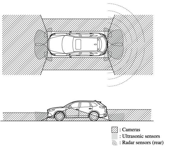
Always confirm the safety of the area around the vehicle with the mirrors and directly with your eyes when driving.
The 360°View Monitor is an auxiliary device which assists the driver in checking the safety of the area around the vehicle.
The shooting range of the cameras and detection range of the sensors are limited. For example, the areas in black at the front and rear of the vehicle image and the seams where each of the camera images merge are blind spots where an obstruction may not be visible. In addition, the extended vehicle width lines and projected vehicle path lines are only to be used as references, and the images on the screen may differ from the actual conditions.
-
Do not use the 360°View Monitor under any of the following conditions.
-
Icy or snow-covered roads.
-
Tyre chains or a temporary spare tyre is installed.
-
The front doors or the liftgate/boot is not fully closed.
-
The vehicle is on a road incline.
-
The door mirrors are retracted.
-
-
Do not hit the front/rear camera, front bumper, and door mirrors forcefully. The camera position or installation angle may shift.
-
The cameras are of a waterproof structure. Do not disassemble, modify, or remove a camera.
-
The camera cover is made of hard plastic, therefore do not apply oil film remover, organic solvents, wax, or coating agents. If any such agent gets on the camera cover, wipe it off using a soft cloth immediately.
-
Do not rub the camera lens forcefully, or clean it with an abrasive or hard brush. Otherwise, it could scratch the camera lens and negatively affect the images.
-
Consult an Authorised Mazda Repairer for repair, painting, or replacement of the front/rear camera, front bumper and door mirrors.
-
Heed the following cautions to assure that the 360°View Monitor operates normally.
-
Do not modify the suspensions.
-
Always use wheels of the specified type and size for the front and rear wheels. Consult an Authorised Mazda Repairer for tyre replacement.
-
-
When the display is cold, images may leave trails or the screen might be darker than usual, making it difficult to check the vehicle surroundings. Always confirm the safety at the front and around the vehicle visually when driving.
-
The method for parking/stopping the vehicle using the 360°View Monitor differs depending on the road circumstances/conditions and the vehicle conditions. When and how much you turn the steering wheel will differ depending on the situation, , therefore always check the vehicle surroundings directly with your eyes while using the system.
Also, before using the system, always make sure that the vehicle can be parked/stopped in the parking/stopping space.
-
If there are water droplets, snow, or mud on the camera lens, wipe it off using a soft cloth. If the camera lens is especially dirty, wash it off with mild detergent.
-
If the area where the camera is installed, such as the liftgate/boot or door mirrors, has been damaged in a vehicle accident, the camera (position, installation angle) may have shifted. Always consult an Authorised Mazda Repairer to have the vehicle inspected.
-
If the camera is subjected to excessive changes in temperature such as by pouring hot water on the camera during cold weather, the 360°View Monitor may not operate normally.
-
If the battery voltage is low, the screen might be temporarily difficult to view, however, this does not indicate a problem.
-
The 360°View Monitor has limitations. Objects under the bumper or near both ends of the bumper cannot be displayed.
-
Obstructions above the upper image range of the camera are not displayed.
-
Under the following conditions, the screen might be difficult to view, however this does not indicate a problem.
-
The temperature near the lens is high/low.
-
Rainy conditions, water droplets on the camera, or high humidity.
-
Mud or foreign matter near the camera.
-
Extremely bright light such as sunlight or headlights hitting the camera lens directly.
-
-
Because the 360°View Monitor camera uses a special lens, the distance displayed on the screen differs from the actual distance.
-
Obstructions displayed on the screen may appear differently than in actuality. (Obstructions may appear fallen, larger, or longer than they actually are.)
-
Do not apply stickers to a camera or the area around it. In addition, do not install accessories or an illuminated number/character number plate to the area around a camera. Otherwise, the camera may not correctly display the surrounding conditions.
Types of Images Displayed on the Screen
Top view/Front view
Displays the image of the area around the vehicle and the vehicle front.

Front wide view
Displays the image of the front of the vehicle (wide-area).

Side view
Displays the image of the left and right sides of the vehicle.

Top view/Rear view
Displays the image of the area around the vehicle and the rear of the vehicle.

Rear wide view
Displays the image of the rear of the vehicle (wide-area).

How to Use the System
Top view/Front view, Front wide view, Side view
Indication
Images are displayed on the screen when the 360°View Monitor switch is pressed with all of the following conditions met.
-
The ignition is switched ON.
-
The selector lever is in a position other than R.

Display switching
You can change the displayed screen by pressing the commander knob or by touching the switch camera icon on the screen while the top view/front view, front wide view, or the side view is displayed.

-
When the selector lever is in R position, the displayed screen does not switch to the top view/front view, front wide view, or the side view.
-
Display of the top view/front view, front wide view, or the side view stops even with the display conditions met if any of the following conditions occurs.
-
When a switch around the commander knob is pressed.
-
The selector lever is shifted to P position (displayed when the selector lever is in a position other than P).
-
(Displayed when vehicle speed is less than 15 km/h (9.3 mph))
-
4 minutes and 30 seconds have passed.
-
The vehicle speed is about 15 km/h (9.3 mph) or faster.
-
-
(Displayed when the vehicle speed is about 15 km/h (9.3 mph) or faster)
-
The vehicle speed is about 15 km/h (9.3 mph) or faster after 8 seconds have passed since pressing the 360°View Monitor switch.
-
Four minutes and 22 seconds have passed from the point when the vehicle speed was less than 15 km/h (9.3 mph) after 8 seconds have passed since pressing the 360° View Monitor switch.
-
-
-
The 360°View Monitor displays the previously displayed screen.
-
The 360° View Monitor settings can be changed as follows.
Refer to Personalisation Features (Search).
-
Automatic display of the 360°View Monitor when the ultrasonic senor detects an obstruction.
-
Automatic display of the 360°View Monitor when the ignition is switched ON.
-
Top view/Rear view, Rear wide view
The top view/rear view, rear wide view displays when all of the following conditions are met.
-
The ignition is switched ON.
-
Selector lever is in R position.
Display switching
The displayed screen can be switched by pressing the commander knob or by touching the switch camera icon on the screen while the top view/rear view, rear wide view is displayed.

-
The top view/rear view and rear wide view automatically display whether or not the 360° View Monitor switch is turned on or off when shifting the selector lever to R position.
-
The setting can be changed to display the top view/front view when shifting from reverse to a forward gear without operating the 360°View Monitor switch to check the front of the vehicle while parallel parking.
Refer to Personalisation Features (Search).
Screen operation/icon
Always stop the vehicle when adjusting the 360°View Monitor image quality.
Do not adjust the 360°View Monitor image quality while driving. If you adjust the 360° View Monitor image quality (such as brightness, contrast, tone, and colour density) while driving, it could lead to an unexpected accident.

Display/Icon |
Content |
|
---|---|---|
![]() |
View status icon |
Indicates which image is displayed among the front view/front wide view/side view/rear view/rear wide view. |
![]() |
Parking sensor status icon |
Indicates that the parking sensor has a problem or it is switched off. |
![]() |
Rear Cross Traffic Alert (RCTA) status icon |
Indicates that the radar sensor (rear) has a problem or it is turned off. |
![]() |
Switch camera icon |
Each time the screen is touched, the display screen switches. |
![]() |
Setting icon |
The image quality for the 360°View Monitor can be adjusted. |
Top View/Front View
Use the top view/front view to assist in checking the safety of the surrounding area when accelerating from a stop, parking, or stopping the vehicle.
Display range

-
In the top view screen, the areas in black at the front and rear of the vehicle image and the seams where each of the camera images merge are blind spots.
-
Because images displayed in the top view screen are processed from each camera, the top view screen may display in the following ways.
-
If an image containing an object with a conspicuous colour is picked up by any of the cameras, the whole screen may be affected and it may display in that colour.
-
Obstructions displayed in the front view may not display on the top view screen.
-
If the position or angle of each camera changes due to tilting of the vehicle, the image may appear distorted.
-
Lines on the road may appear distorted at the seams where each of the camera images merge.
-
The entire screen may appear bright/dark depending on the illumination level around any of the cameras.
-
Viewing the screen

Display/Icon |
Content |
|
---|---|---|
![]() |
Parking sensor view |
Displays the parking sensor detection condition when the parking sensor is activated. For details, refer to the parking sensor obstruction detection indication and warning sound. Refer to Parking Sensor System (Search). |
![]() |
Tyre icon |
Indicates the tyre direction. Moves in conjunction with the steering wheel operation. |
![]() |
Projected vehicle path lines (amber) |
Indicates the approximate projected path of the vehicle. Moves in conjunction with the steering wheel operation. a) Indicates the path where the edge of the front bumper is expected to travel. b) Indicates the path where the inner side of the vehicle is expected to travel. |
![]() |
Extended vehicle width lines and distance guide lines (red/blue) |
Indicates the approximate width of the vehicle and the distance (from front end of bumper) in front of the vehicle.
|
![]() |
Projected vehicle path distance guide lines (red/amber) |
Indicates the distance (from front end of bumper) in front of the vehicle.
|
The parking sensor detection range has limitations. For example, obstructions closing in from the side and objects short in height may not be detected. Always confirm the safety around the vehicle visually when driving.
For details, refer to the parking sensor obstruction detection indication and warning sound.
Refer to Parking Sensor System (Search).
The setting can be changed so that the projected vehicle path lines are not displayed.
Refer to Personalisation Features (Search).
How to use the projected vehicle path line function

Make sure that there are no obstructions within the projected vehicle path lines.
Drive the vehicle forward while turning the steering wheel so that no obstructions come within the projected vehicle path lines.
Front Wide View
Use the front wide view to assist in checking the safety of the surrounding area when accelerating from a stop or entering a T-shaped intersection and intersection.
Display range

Viewing the screen

Display/Icon |
Content |
|
---|---|---|
![]() |
Extended vehicle width lines and distance guide lines (red/blue) |
Indicates the approximate width of the vehicle and the distance (from front end of bumper) in front of the vehicle.
|
-
The parking sensor obstruction detection indication does not display. Switch the screen display to the top view/front view or side view display if the parking sensor warning sound is activated.
-
The front wide view screen displays the image in front of the vehicle at a wide angle and corrects the image to help detect approaching obstructions from the side. Therefore, it differs from the actual view.
Side View
Use the side view to assist in checking the safety of the surrounding area when accelerating from a stop, parking, or stopping the vehicle.
Display range

Viewing the screen

Display/Icon |
Content |
|
---|---|---|
![]() |
Parking sensor view |
Displays the parking sensor detection condition when the parking sensor is activated. For details, refer to the parking sensor obstruction detection indication and warning sound. Refer to Parking Sensor System (Search). |
![]() |
Projected vehicle path lines (amber) |
Indicates the approximate projected path of the vehicle. Moves in conjunction with the steering wheel operation. The projected vehicle path lines (amber) indicate the path the inner side of the vehicle is expected to travel. |
![]() |
Vehicle parallel guide lines (blue) |
Indicates the approximate vehicle width including the door mirrors. |
![]() |
Vehicle front end guide lines (blue) |
Indicates the point about 0.25 m (9.8 in) from the front edge of the vehicle (front edge of the bumper). |
The setting can be changed so that the projected vehicle path lines are not displayed.
Refer to Personalisation Features (Search).
How to use the projected vehicle path line function

Make sure that there are no obstructions within the projected vehicle path lines.
Turn the steering wheel so that the projected vehicle path lines travel inside of the obstruction (A), and drive the vehicle forward until it passes the obstruction.
If the projected vehicle path lines are on an obstruction (B) or outside of the obstruction (C), the vehicle may contact the obstruction when turning the vehicle sharply.
-
The parking sensor detection range has limitations. For example, obstructions closing in from the side and objects short in height may not be detected. Always confirm the safety around the vehicle visually when driving.
For details, refer to the parking sensor obstruction detection indication and warning sound.
Refer to Parking Sensor System (Search).
-
Do not turn the steering wheel any more until the vehicle has passed the obstruction, even if the obstruction is not visible on the side view image. If the steering wheel is turned even more, the vehicle may contact the obstruction if it is turned sharply.
-
Because there might be a difference between the image displayed on the screen and the actual conditions, always check the safety of the surrounding area using the mirrors and directly with your eyes when driving.
-
Even though the object displayed on the screen, such as a road curb or a division line of a parking space, and the vehicle parallel guide lines appear parallel, they may not actually be parallel.
Top View/Rear View
Use the top view/rear view to assist in checking the safety of the surrounding area when accelerating from a stop, parking, or stopping the vehicle.
Range of displayed screen image

-
In the top view screen, the areas in black at the front and rear of the vehicle image and the seams where each of the camera images merge are blind spots.
-
Because images displayed in the top view screen are processed from each camera, the top view screen may display in the following ways.
-
If an image containing an object with a conspicuous colour is picked up by any of the cameras, the whole screen may be affected and it may display in that colour.
-
Obstructions displayed in the rear view may not display on the top view screen.
-
If the position or angle of each camera changes due to tilting of the vehicle, the image may appear distorted.
-
Lines on the road may appear distorted at the seams where each of the camera images merge.
-
The entire screen may appear bright/dark depending on the illumination level around any of the cameras.
-
Viewing the screen

Display/Icon |
Content |
|
---|---|---|
![]() |
Parking sensor view |
Displays the parking sensor detection condition when the parking sensor is activated. For details, refer to the parking sensor obstruction detection indication and warning sound. Refer to Parking Sensor System (Search). |
![]() |
Tyre icon |
Indicates the tyre direction. Moves in conjunction with the steering wheel operation. |
![]() |
Projected vehicle path lines (amber) |
Indicates the approximate projected path of the vehicle. Moves in conjunction with the steering wheel operation. a) Indicates the path where the rear wheels are expected to travel. b) Indicates the path where the outer side of the vehicle is expected to travel. |
![]() |
Extended vehicle width lines and distance guide lines (red/blue) |
These guide lines indicate the approximate width of the vehicle and distance to a point measured from the rear of the vehicle (from the end of the bumper).
|
![]() |
Projected vehicle path distance guide lines (red/amber) |
These guide lines indicate the approximate distance to a point measured from the rear of the vehicle (from the end of the bumper).
|
![]() |
Blind Spot Monitoring (BSM) warning lights |
Indicates when the Rear Cross Traffic Alert (RCTA) has operated. For details, refer to Rear Cross Traffic Alert (RCTA). Refer to Rear Cross Traffic Alert (RCTA) (Search). |
The setting can be changed so that the projected vehicle path lines are not displayed.
Refer to Personalisation Features (Search).
How to use the projected vehicle path line function
-
The front of the vehicle swings out wide when turning the steering wheel while reversing. Maintain sufficient distance between the vehicle and an obstruction.
-
The parking sensor detection range has limitations. For example, obstructions closing in from the side and objects short in height may not be detected. Always confirm the safety around the vehicle visually when driving.
For details, refer to the parking sensor obstruction detection indication and warning sound.
Refer to Parking Sensor System (Search).
-
Because there might be a difference between the image displayed on the screen, such as indicated in the following, and the actual conditions when parking, always check the safety at the rear of the vehicle and the surrounding area directly with your eyes.
-
Even though the back end of the parking space (or garage) displayed on the screen and distance guide lines appear parallel, they may not actually be parallel.
-
When parking in a space with a division line on only one side of the parking space, even though the division line and the vehicle width guide line appear parallel, they may not actually be parallel.
-
-
The following shows an example of vehicle parking with the steering wheel turned to the right while backing up the vehicle. When backing into a parking space from the opposite direction, the steering operation is reversed.
-
Back the vehicle into the parking space by turning the steering wheel so that the vehicle enters the centre of the parking space.
-
After the vehicle starts entering the parking space, stop and adjust the steering wheel so that the distance between the vehicle width lines and the sides of the parking space on the left and right are roughly equal, and then continue backing up slowly.
-
Once the vehicle width lines and the sides of the parking space on the left and right are parallel, straighten the wheels and back the vehicle slowly into the parking space. Continue checking the vehicle's surroundings and then stop the vehicle in the best possible position. (If the parking space has division lines, check whether the vehicle width guide lines are parallel to them.)
Rear Wide View
Use the rear wide view to assist in checking the safety of the surrounding area when accelerating from a stop, parking, or stopping the vehicle.
Range of displayed screen image

Viewing the screen

Display/Icon |
Content |
|
---|---|---|
![]() |
Extended vehicle width lines and distance guide lines (red/blue) |
These guide lines indicate the approximate width of the vehicle and distance to a point measured from the rear of the vehicle (from the end of the bumper).
|
![]() |
Blind Spot Monitoring (BSM) warning lights |
Indicates when the Rear Cross Traffic Alert (RCTA) has operated. For details, refer to Rear Cross Traffic Alert (RCTA). Refer to Rear Cross Traffic Alert (RCTA) (Search). |
-
The parking sensor obstruction detection indication does not display. Switch the screen display to the top view/rear view display if the parking sensor warning sound is activated.
-
The rear wide view screen displays the image at the rear of the vehicle at a wide angle and corrects the image to help detect approaching obstructions from the side. Therefore, it differs from the actual view.
Margin of Error Between Road Surface on Screen and Actual Road Surface
There might be some margin of error between the road surface appearing on the screen and the actual road surface. A margin of error in the perceived distance could lead to an accident, therefore be aware of the following conditions which can more easily produce errors in the perceived distance.
The vehicle tilts due to weight of passengers and cargo.
If the vehicle is tilted, obstructions picked up by a camera can appear farther or closer than the actual distance from the vehicle.
Front camera

Side camera

Rear camera

There is a steep up or down grade in the road at the front or rear of the vehicle
If there is a steep up or down grade in the road at the front or rear of the vehicle, obstructions picked up by the camera can appear farther or closer than the actual distance from the vehicle.
Front camera

Side camera

Rear camera

If the vehicle is on a slope, obstructions taken by the camera can appear farther or closer than the actual distance from the vehicle.
Three-dimensional object at vehicle front or rear
Because the vehicle front end guide lines (side camera) or the distance guide lines (rear camera) are displayed based on a flat surface, the distance to the three-dimensional object displayed on the screen is different from the actual distance.
Side camera

Rear camera

System Problem Indication
Centre display indication |
Cause |
Action to be taken |
---|---|---|
“No image signal reception” is displayed |
The control unit might be damaged. |
Have your vehicle inspected by an Authorised Mazda Repairer. |
Screen is pitch-black and blank |
The camera might be damaged. |
|
Forward Sensing Camera (FSC)
Your vehicle is equipped with a Forward Sensing Camera (FSC). The Forward Sensing Camera (FSC) is positioned near the rearview mirror and used by the following systems.
-
High Beam Control System (HBC)
-
Adaptive LED Headlights (ALH)
-
Driver Attention Alert (DAA)
-
Lane-keep Assist System (LAS) & Lane Departure Warning System (LDWS)
-
Traffic Sign Recognition System (TSR)
-
Advanced Smart City Brake Support (Advanced SCBS)
-
Mazda Radar Cruise Control with Stop & Go function (MRCC with Stop & Go function)
-
Smart Brake Support (SBS)

The Forward Sensing Camera (FSC) determines the conditions ahead of the vehicle while travelling at night and detects traffic lanes. The distance in which the Forward Sensing Camera (FSC) can detect objects varies depending on the surrounding conditions.
Do not modify the suspension:
If the vehicle height or inclination is changed, the system will not be able to correctly detect vehicles ahead. This will result in the system not operating normally or mistakenly operating, which could cause a serious accident.
-
Do not apply accessories, stickers or film to the windscreen near the Forward Sensing Camera (FSC).
If the area in front of the Forward Sensing Camera (FSC) lens is obstructed, it will cause the system to not operate correctly. Consequently, each system may not operate normally which could lead to an unexpected accident.
-
Do not disassemble or modify the Forward Sensing Camera (FSC).
Disassembly or modification of the Forward Sensing Camera (FSC) will cause a malfunction or mistaken operation. Consequently, each system may not operate normally which could lead to an unexpected accident.
-
Heed the following cautions to assure the correct operation of the Forward Sensing Camera (FSC).
-
Be careful not to scratch the Forward Sensing Camera (FSC) lens or allow it to get dirty.
-
Do not remove the Forward Sensing Camera (FSC) cover.
-
Do not place objects on the instrument panel which reflect light.
-
Always keep the windscreen glass around the camera clean by removing dirt or fogging. Use the windscreen defroster to remove fogging on the windscreen.
-
Consult an expert repairer, we recommend an Authorised Mazda Repairer regarding cleaning the interior side of the windscreen around the Forward Sensing Camera (FSC).
-
Consult an expert repairer, we recommend an Authorised Mazda Repairer before performing repairs around the Forward Sensing Camera (FSC).
-
The Forward Sensing Camera (FSC) is installed to the windscreen. Consult an expert repairer, we recommend an Authorised Mazda Repairer for windscreen repair and replacement.
-
When cleaning the windscreen, do not allow glass cleaners or similar cleaning fluids to get on the Forward Sensing Camera (FSC) lens. In addition, do not touch the Forward Sensing Camera (FSC) lens.
-
When performing repairs around the rearview mirror, consult an expert repairer, we recommend an Authorised Mazda Repairer.
-
Consult an expert repairer, we recommend an Authorised Mazda Repairer regarding cleaning of the camera lens.
-
Do not hit or apply strong force to the Forward Sensing Camera (FSC) or the area around it. If the Forward Sensing Camera (FSC) is severely hit or if there are cracks or damage caused by flying gravel or debris in the area around it, stop using the following systems and consult an expert repairer, we recommend an Authorised Mazda Repairer.
-
High Beam Control System (HBC)
-
Adaptive LED Headlights (ALH)
-
Driver Attention Alert (DAA)
-
Lane-keep Assist System (LAS) & Lane Departure Warning System (LDWS)
-
Traffic Sign Recognition System (TSR)
-
Advanced Smart City Brake Support (Advanced SCBS)
-
Mazda Radar Cruise Control with Stop & Go function (MRCC with Stop & Go function)
-
Smart Brake Support (SBS)
-
-
The direction in which the Forward Sensing Camera (FSC) is pointed has been finely adjusted. Do not change the installation position of the Forward Sensing Camera (FSC) or remove it. Otherwise, it could result in damage or malfunction.
-
-
Always use tyres for all wheels that are of the specified size, and the same manufacturer, brand, and tread pattern. In addition, do not use tyres with significantly different wear patterns on the same vehicle as the system may not operate normally.
-
The Forward Sensing Camera (FSC) includes a function for detecting a soiled windscreen and informing the driver, however, depending on the conditions, it may not detect plastic shopping bags, ice or snow on the windscreen. In such cases, the system cannot accurately determine a vehicle ahead and may not be able to operate normally. Always drive carefully and pay attention to the road ahead.
-
In the following cases, the Forward Sensing Camera (FSC) cannot detect target objects correctly, and each system may be unable to operate normally.
-
The height of the vehicle ahead is low.
-
You drive your vehicle at the same speed as the vehicle ahead.
-
Headlights are not turned on during the night or when going through a tunnel.
-
-
In the following cases, the Forward Sensing Camera (FSC) may not be able to detect target objects correctly.
-
Under bad weather condition, such as rain, fog and snow.
-
The window washer is being used or the windscreen wipers are not used when it's raining.
-
Ice, fog, snow, frost, rainfall, dirt, or foreign matter such as a plastic bag is stuck on the windscreen.
-
Trucks with low loading platforms and vehicles with an extremely low or high profile.
-
When driving next to walls with no patterning (including fences and longitudinally striped walls).
-
The tail lights of the vehicle ahead are turned off.
-
A vehicle is outside the illumination range of the headlights.
-
The vehicle is making a sharp turn, or ascending or descending a steep slope.
-
Entering or exiting a tunnel.
-
Heavy luggage is loaded causing the vehicle to tilt.
-
Strong light is shone at the front of the vehicle (back light or high-beam light from on-coming vehicles).
-
There are many light emitters on the vehicle ahead.
-
When the vehicle ahead is not equipped with tail lights or the tail lights are turned off at nighttime.
-
Elongated luggage or cargo is loaded onto installed roof rails and covers the Forward Sensing Camera (FSC).
-
Exhaust gas from the vehicle in front, sand, snow, and water vapour rising from manholes and grating, and water splashed into the air.
-
When towing a malfunctioning vehicle.
-
The vehicle is driven with tyres having significantly different wear.
-
The vehicle is driven on down slopes or bumpy roads.
-
There are water puddles on the road.
-
The surroundings are dark such as during the night, early evening, or early morning, or in a tunnel or indoor parking lot.
-
The illumination brightness of the headlights is reduced or the headlight illumination is weakened due to dirt or a deviated optical axis.
-
The target object enters the blind spot of the Forward Sensing Camera (FSC).
-
A person or object bursts onto the road from the shoulder or cuts right in front of you.
-
You change lanes and approach a vehicle ahead.
-
When driving extremely close to the target object.
-
Tyre chains or a temporary spare tyre is installed.
-
The vehicle ahead has a special shape. For example, a vehicle towing a trailer house or a boat, or a vehicle carrier carrying a vehicle with its front pointed rearward.
-
-
If the Forward Sensing Camera (FSC) cannot operate normally due to backlight or fog, the system functions related to the Forward Sensing Camera (FSC) are temporarily stopped and the following warning lights turn on. However, this does not indicate a malfunction.
-
High Beam Control System (HBC) warning light (amber)
-
Adaptive LED Headlights (ALH) warning light (amber)
-
Lane-keep Assist System (LAS) & Lane Departure Warning System (LDWS) warning indication
-
Mazda Radar Cruise Control with Stop & Go function (MRCC with Stop & Go function) warning indication
-
Smart Brake Support/Smart City Brake Support (SBS/SCBS) warning indication (amber)
-
-
If the Forward Sensing Camera (FSC) cannot operate normally due to high temperatures, the system functions related to the Forward Sensing Camera (FSC) are temporarily stopped and the following warning lights turn on. However, this does not indicate a malfunction. Cool down the area around the Forward Sensing Camera (FSC) such as by turning on the air conditioner.
-
High Beam Control System (HBC) warning light (amber)
-
Adaptive LED Headlights (ALH) warning light (amber)
-
Lane-keep Assist System (LAS) & Lane Departure Warning System (LDWS) warning indication
-
Mazda Radar Cruise Control with Stop & Go function (MRCC with Stop & Go function) warning indication
-
Smart Brake Support/Smart City Brake Support (SBS/SCBS) warning indication (amber)
-
-
If the Forward Sensing Camera (FSC) detects that the windscreen is dirty or foggy, the system functions related to the Forward Sensing Camera (FSC) are temporarily stopped and the following warning lights turn on. However, this does not indicate a problem. Remove the dirt from the windscreen or press the defroster switch and defog the windscreen.
-
High Beam Control System (HBC) warning light (amber)
-
Adaptive LED Headlights (ALH) warning light (amber)
-
Lane-keep Assist System (LAS) & Lane Departure Warning System (LDWS) warning indication
-
Mazda Radar Cruise Control with Stop & Go function (MRCC with Stop & Go function) warning indication
-
Smart Brake Support/Smart City Brake Support (SBS/SCBS) warning indication (amber)
-
-
If there are recognizable cracks or damage caused by flying gravel or debris on the windscreen, always have the windscreen replaced. Consult an Authorised Mazda Repairer for replacement.
-
The recognises pedestrians when all of the following conditions are met:
-
The Forward Sensing Camera (FSC) height of a pedestrian is about 1 to 2 meters.
-
An outline such as the head, both shoulders, or the legs can be determined.
-
-
In the following cases, the Forward Sensing Camera (FSC) may not be able to detect target objects correctly:
-
Multiple pedestrians are walking, or there are groups of people.
-
A pedestrian is close to a separate object.
-
A pedestrian is crouching, lying, or slouching.
-
A pedestrian suddenly jumps into the road right in front of the vehicle.
-
A pedestrian opens an umbrella, or is carrying large baggage or articles.
-
A pedestrian is in a dark location such as during the night, or blends into the background by wearing clothes matching the background colour.
-
Ultrasonic Sensor (Rear)
The ultrasonic sensors (rear) function by emitting ultrasonic waves which are reflected off obstructions at the rear and the returning ultrasonic waves are picked up by the ultrasonic sensors (rear).

The ultrasonic sensors (rear) are mounted in the rear bumper.
Front Camera/Side Cameras/Rear Camera (Some Models)
Your vehicle is equipped with a front camera, side cameras, and a rear camera. The 360° View Monitor uses each camera.
The front camera, side cameras, and rear camera shoot images of the area surrounding the vehicle.
Each camera is installed to the following positions.
