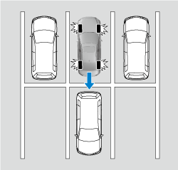
Smart Brake Support [Rear] (SBS-R)
The SBS-R is a system which is designed to reduce damage in the event of a collision by operating the brake control (SBS brake) when the system’s sensors detect an obstruction at the rear of the vehicle while driving at a speed of about 2 to 8 km/h (2 to 4 mph) and the system determines that a collision is unavoidable.
Do not rely completely on the SBS-R system:
-
The SBS-R system is only designed to reduce damage in the event of a collision. Over reliance on the system leading to the accelerator pedal or brake pedal being mistakenly operated could result in an accident.
-
To assure the correct operation of the SBS-R, heed the following cautions.
-
Do not apply a sticker to a rear ultrasonic sensor and rear camera. Otherwise, the rear ultrasonic sensor and rear camera may not be able to detect vehicles or obstructions which could result in an accident.
-
Do not disassemble a rear ultrasonic sensor and rear camera.
-
If cracks or damage caused by flying gravel or debris is visible around a rear ultrasonic sensor and rear camera, stop using the SBS-R system immediately and have your vehicle inspected by an expert repairer, we recommend an Authorised Mazda Repairer. If the vehicle continues to be driven with cracks or scratch marks left around an ultrasonic sensor, the system may operate unnecessarily and cause an unexpected accident.
Refer to Stopping the Smart Brake Support [Rear] (SBS-R) System Operation (Search).
-
Consult an expert repairer, we recommend an Authorised Mazda Repairer for rear bumper replacement.
-
Do not modify the suspension:
If the vehicle height or inclination is changed, the SBS-R system may not operate correctly because it cannot detect obstructions correctly.
Do not apply a strong force to a rear ultrasonic sensor and rear camera:
When washing the vehicle, do not spray highly pressurised water against a rear ultrasonic sensor and rear camera, or rub it strongly. In addition, do not hit the rear bumper forcefully when loading and unloading cargo Otherwise, the sensors may not detect obstructions correctly which could cause the SBS-R system to not operate normally, or it could operate unnecessarily.


-
When driving off-road in areas where there is grass or foliage, it is recommended that the SBS-R system be turned off.
-
Always use tyres of the specified size and the same manufacturer, brand, and tread pattern on all 4 wheels. In addition, do not use tyres with significantly different wear patterns on the same vehicle. Otherwise, the SBS-R system may not operate normally.
-
If ice or snow is stuck on the rear ultrasonic sensor and rear camera they may not be able to detect obstructions correctly depending on the conditions. In such cases, the system may not be able to perform controls correctly. Always drive carefully and pay attention to the rear of the vehicle.
-
The vehicle posture changes depending on the accelerator pedal, brake pedal and steering wheel operations, which could make it difficult for the system to recognise an obstruction, or it could facilitate unnecessary detection. In such cases, the SBS-R may or may not operate.
-
The SBS-R system will operate under the following conditions.
-
The engine is running.
-
The shift lever (manual transmission vehicle) or the selector lever (automatic transmission vehicle) is in the R (reverse) position.
-
The slope is less than 5 %.
-
i-ACTIVSENSE warning indication/warning light is not displayed in the multi-information display.
-
The vehicle speed is between about 2 to 8 km/h (2 to 4 mph).
-
The SBS-R is not turned off.
-
The DSC is not malfunctioning.
-
-
In the following cases, the rear ultrasonic sensor and rear camera cannot detect obstructions and the SBS-R may not operate.
-
The height of the obstruction is low such as low walls or trucks with low loading platforms.
-
The height of the obstruction is high such as trucks with high loading platforms.
-
The obstruction is small.
-
The obstruction is thin such as a signpost.
-
The surface of the obstruction is not pointed vertically relative to the vehicle.
-
The obstruction is soft such as a hanging curtain or snow stuck to a vehicle.
-
The obstruction is shaped irregularly.
-
The obstruction is extremely close.
-
-
In the following cases, the rear ultrasonic sensor and rear camera cannot detect obstructions correctly and the SBS-R may not operate.
-
Something is stuck on the bumper near a rear ultrasonic sensor.
-
The brake or accelerator pedal is operated.
-
There is another obstruction near one obstruction.
-
During inclement weather such as rain, fog and snow.
-
High or low humidity.
-
High or low temperatures
-
Strong winds.
-
The path of travel is not flat.
-
Heavy luggage is loaded in the luggage compartment or on the rear seat.
-
Objects such as a wireless aerial, fog light, or illuminated number plate is installed near a rear ultrasonic sensor.
-
The orientation of a rear ultrasonic sensor has deviated for reasons such as a collision.
-
The vehicle is affected by other sound waves such as the horn, engine noise, ultrasonic sensor of another vehicle.
-
-
In the following cases, a rear ultrasonic sensor and rear camera may detect something as a target obstruction which could cause the SBS-R system to operate.
-
Driving on a steep slope.
-
Wheel blocks.
-
Hanging curtains, gate poles such as at toll gates and railroad crossing.
-
When travelling near objects such as foliage, barriers, vehicles, walls, and fences along a road.
-
When driving off-road in areas where there is grass and forage.
-
When passing through low gates, narrow gates, car washing machines, and tunnels.
-
A trailer is connected.
-
A bright light source such as sunlight hits the rear camera.
-
The surroundings are dark.
-
An exterior accessory such as a bicycle carrier is installed around the rear sonar.
-
-
(Manual transmission)
If the vehicle is stopped by the SBS-R operation and the clutch pedal is not depressed, the engine stops.
-
When the system operates, the user is notified by the multi-information display.
-
The collision warning beep sounds intermittently while the SBS-R brake is operating.
-
If the vehicle is stopped by the SBS-R operation and the brake pedal is not depressed, displaying in meter “Emergency Braking Activated. Depress Brake Pedal to Hold Stop”, after about 2 seconds and the SBS-R brake is automatically released.
-
If a Mazda genuine trailer hitch is used, the SBS-R is automatically turned off.