Owner Maintenance

Bonnet


Always check that the bonnet is closed and securely locked:

A bonnet that is not closed and securely locked is dangerous as it could fly open while the vehicle is moving and block the driver's vision which could result in a serious accident.

Closing the Bonnet

  1. Check under the bonnet area to make certain all filler caps are in place and all loose items (e.g. tools, oil containers, etc.) have been removed.

  2. Lift the bonnet, grasp the padded area on the support rod, and secure the support rod in the clip. Verify that the support rod is secured in the clip before closing the bonnet.


  3. Lower the bonnet slowly to a height of about 20 cm (7.9 in) above its closed position and then let it drop.


When closing the bonnet, do not push it excessively such as by applying your weight. Otherwise, the bonnet could be deformed.

Inspecting Engine Oil Level

  1. Be sure the vehicle is on a level surface.

  2. Warm up the engine to normal operating temperature.

  3. Turn it off and wait at least 5 minutes for the oil to return to the sump.

  4. Pull out the dipstick, wipe it clean, and reinsert it fully.


  5. Pull it out again and examine the level.

    The level is normal if it is between the MIN and MAX marks.

    If it is near or below MIN, add enough oil to bring the level to MAX.


    Do not overfill the engine oil. This may cause engine damage.

  6. Make sure the O-ring on the dipstick is positioned properly before reinserting the dipstick.

  7. Reinsert the dipstick fully.

Inspecting Coolant Level


Do not use a match or live flame in the engine compartment. DO NOT ADD COOLANT WHEN THE ENGINE IS HOT:

A hot engine is dangerous. If the engine has been running, parts of the engine compartment can become very hot. You could be burned. Carefully inspect the engine coolant in the coolant reservoir, but do not open it.

Pull over to a safe location, then switch the ignition off and make sure the fan is not running before attempting to work near the cooling fan:

Working near the cooling fan when it is running is dangerous. The fan could continue running indefinitely even if the engine has stopped and the engine compartment temperature is high. You could be hit by the fan and seriously injured.

Do not remove either cooling system cap when the engine and radiator are hot:

When the engine and radiator are hot, scalding coolant and steam may shoot out under pressure and cause serious injury.


Changing the coolant should be done by an expert repairer, we recommend an Authorised Mazda Repairer.

Inspect the antifreeze protection and coolant level in the coolant reservoir at least once a year―at the beginning of the winter season―and before travelling where temperatures may drop below freezing.


Inspect the condition and connections of all cooling system and heater hoses.

Replace any that are swollen or deteriorated.


The coolant should be at full in the radiator and between the FULL and LOW marks on the coolant reservoir when the engine is cool.


If it is at or near LOW, add enough coolant to the coolant reservoir to provide freezing and corrosion protection and to bring the level to FULL.

Securely tighten the coolant reservoir tank cap after adding coolant.


  • Radiator coolant will damage paint.

    Rinse it off quickly if spilled.

  • If the “FL22” mark is shown on or near the cooling system cap, use of FL-22 is recommended when replacing engine coolant. Using engine coolant other than FL-22 may cause serious damage to the engine and cooling system.


If the coolant reservoir is empty or new coolant is required frequently, consult an expert repairer, we recommend an Authorised Mazda Repairer.

Battery Maintenance

To get the best service from a battery:

  • Keep it securely mounted.

  • Keep the top clean and dry.

  • Keep terminals and connections clean, tight, and coated with petroleum jelly or terminal grease.

  • Rinse off spilled electrolyte immediately with a solution of water and baking soda.

  • If the vehicle will not be used for an extended time, disconnect the battery leads and charge the battery every six weeks.

Tyre Rotation


Rotate tyres periodically:

Irregular tyre wear is dangerous. To equalize tread wear for maintaining good performance in handling and braking, rotate the tyres every 10,000 km (6,250 miles), or sooner if irregular wear develops.

During rotation, inspect them for correct balance.


Because your vehicle is not equipped with a spare tyre, you cannot do a tyre rotation safely with the jack that comes with your vehicle. Have an expert repairer, we recommend an Authorised Mazda Repairer perform tyre rotation.


Also, inspect them for uneven wear and damage. Abnormal wear is usually caused by one or a combination of the following:


  • Incorrect tyre pressure

  • Improper wheel alignment

  • Out-of-balance wheel

  • Severe braking

After rotation, inflate all tyre pressures to specification (Search) and inspect the wheel nuts for tightness.


Rotate unidirectional tyres and radial tyres that have an asymmetrical tread pattern or studs only from front to rear, not from side to side. Tyre performance will be reduced if rotated from side to side.

(With limited-slip differential)

Do not use the following:

  • Tyres not of the designated size

  • Tyres of different sizes or types at the same time

  • Tyres not sufficiently inflated

If these instructions are not followed, the rotation of the left and right wheels will be different and will thus apply a constant load on the limited-slip differential.

This will cause a malfunction.

Replacing a Tyre


Always use tyres that are in good condition:

Driving with worn tyres is dangerous. Reduced braking, steering, and traction could result in an accident.

Replace all four tyres at the same time:

Replacing just one tyre is dangerous. It could cause poor handling and poor braking resulting in loss of vehicle control. Mazda strongly recommends that you replace all four tyres at the same time.

If a tyre wears evenly, a wear indicator will appear as a solid band across the tread.

Replace the tyre when this happens.

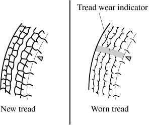
You should replace the tyre before the band crosses the entire tread.

Replacing Exterior Light Bulbs

Headlights, Running lights (LED type), Position lights, High-mount brake light, Brake lights, Tail lights, Rear fog light (Some Models)

The LED bulb cannot be replaced as a single unit because it is an integrated unit.

The LED bulb has to be replaced with the unit. We recommend an Authorised Mazda Repairer when the replacement is necessary.

Running lights (Bulb type)

  1. Make sure the ignition is switched off, and the headlight switch is off.

  2. Pull the centre of each plastic retainer and remove the retainers.


  3. Turn the screw anticlockwise and remove it, and then partially peel back the mudguard.


  4. Turn the socket and bulb assembly anticlockwise and remove it.

  5. Disconnect the bulb from the socket.


  6. Install the new bulb in the reverse order of the removal procedure.

Front direction indicator lights

  1. Make sure the ignition is switched off, and the headlight switch is off.

  2. If you are changing the right bulb, start the engine, turn the steering wheel all the way to the right, and turn off engine. If you are changing the left bulb, turn the steering wheel to the left.

  3. Pull the centre of each plastic retainer and remove the retainers, and then partially peel back the mudguard.


  4. Disconnect the connector from the unit by pressing the tab on the connector with your finger and pulling the connector rearward.


  5. Turn the socket and bulb assembly anticlockwise and remove it.

  6. Disconnect the bulb from the socket.


  7. Install the new bulb in the reverse order of the removal procedure.

Side direction indicator lights

  1. Make sure the ignition is switched off, and the headlight switch is off.

  2. If you are changing the right bulb, start the engine, turn the steering wheel all the way to the right, and turn off engine. If you are changing the left bulb, turn the steering wheel to the left.

  3. Pull the centre of each plastic retainer and remove the retainers, and then partially peel back the mudguard.


  4. Remove the unit by pressing the tab on the unit with your finger and pulling the unit forward.


  5. Detach the electrical connector from the unit by pulling it to the rear.


  6. Install the new side direction indicator unit in the reverse order of the removal procedure.

Rear direction indicator lights

  1. Make sure the ignition is switched off, and the headlight switch is off.

  2. Pull the centre of each plastic retainer and remove the retainers and the boot end trim.


  3. Disconnect the connector from the unit by pressing the tab on the connector with your finger and pulling the connector downward.


  4. Pull the centre of each plastic retainer and remove the retainers, and then partially peel back the boot side trim.


  5. To provide a hole for inserting a finger to remove the rear combination lamp unit later in the procedure, pinch the top and bottom of the grommet shown in the figure and press it out of the hole in the direction of the rear combination lamp unit.


  6. Apply protective tape as shown in the figure. Otherwise, the rear combination lamp unit will contact the body and may scratch or damage it.

    Always apply three layers of protective tape to the area indicated in the figure.


    • Do not use tape with strong adhesive strength. Otherwise, the vehicle paint may peel off.

    • Always apply three layers of protective tape to the area indicated in the figure. Otherwise, the body may become scratched or damaged when pulling out the rear combination lamp unit.

  7. Remove the screw and nut.


  8. To remove the rear combination lamp unit, insert your finger from inside the boot and into the hole from which the grommet was removed in Step 5, and while holding the lamp lens (round part) of the rear combination lamp with your hand, press the rear combination lamp unit until the hook detaches from the clip.


  9. After the hook is detached, pull out the rear combination lamp unit in the direction of the arrow and remove it.


    Carefully pull out the rear combination lamp unit when removing it from the body.

    The wiring may become damaged if the rear combination lamp unit is forcefully pulled out.

  10. Turn the socket and bulb assembly anticlockwise and remove it.

  11. Disconnect the bulb from the socket.


  12. Install the new bulb in the reverse order of the removal procedure.

Reverse lights

  1. Make sure the ignition is switched off, and the headlight switch is off.

  2. Turn the socket and bulb assembly anticlockwise and remove it.

  3. Disconnect the bulb from the socket.


  4. Install the new bulb in the reverse order of the removal procedure.

Number plate lights

  1. Make sure the ignition is switched off, and the headlight switch is off.

  2. Remove the unit by pressing the tab on the unit with your finger and pulling the unit downward.


  3. Turn the socket and bulb assembly anticlockwise and remove it.

  4. Disconnect the bulb from the socket.


  5. Install the new bulb in the reverse order of the removal procedure.

Replacing Interior Light Bulbs

Overhead light

  1. Wrap a small flathead screwdriver with a soft cloth to prevent damage to the lens, and then remove the lens by carefully prying on the edge of the lens with the flathead screwdriver.

  2. Disconnect the bulb by pulling it out.


  3. Install the new bulb in the reverse order of the removal procedure.

Boot light

  1. Wrap a small flathead screwdriver with a soft cloth to prevent damage to the lens, and then remove the lens by carefully prying on the edge of the lens with the flathead screwdriver.


  2. Disconnect the connector from the unit.

  3. Disconnect the bulb by pulling it out.


  4. Install the new bulb in the reverse order of the removal procedure.

Fuse Replacement

Replacing the fuses on the vehicle's left side

If the electrical system does not work, first inspect the fuses on the vehicle's left side.


  1. Make sure the ignition is switched off, and other switches are off.

  2. Open the fuse panel cover.

  3. Pull the fuse straight out with the fuse puller provided on the fuse block located in the engine compartment.

  4. Inspect the fuse and replace it if it is blown.

  5. Insert a new fuse of the same amperage rating, and make sure it fits tightly. If it does not fit tightly, have an expert install it. We recommend an Authorised Mazda Repairer.

    If you have no spare fuses, borrow one of the same rating from a circuit not essential to vehicle operation, such as the AUDIO or OUTLET circuit.


    Always replace a fuse with a genuine Mazda fuse or equivalent of the same rating. Otherwise you may damage the electric system.

  6. Reinstall the cover and make sure that it is securely installed.

Replacing the fuses under the bonnet

If the headlights or other electrical components do not work and the fuses in the cabin are normal, inspect the fuse block under the bonnet. If a fuse is blown, it must be replaced. Follow these steps:


  1. Make sure the ignition is switched off, and other switches are off.

  2. Remove the fuse block cover.


    If the lock is forcefully opened, the fuse block cover may come in contact with the frame when it is removed and become scratched.

    When removing the cover, remove it slowly according to the following procedure.

    1. Disengage the rear lock by pressing down on the front tab with your fingers.

    2. Remove the front tab while slightly lifting the front of the cover.

    3. Remove the cover while lifting it and sliding it to the rear.

  3. If any fuse but the MAIN fuse is blown, replace it with a new one of the same amperage rating.


    Do not replace the main fuse by yourself. Have an Authorised Mazda Repairer perform the replacement:

    Replacing the fuse by yourself is dangerous because the MAIN fuse is a high current fuse. Incorrect replacement could cause an electrical shock or a short circuit resulting in a fire.

  4. Reinstall the cover and make sure that it is securely installed.

Fuse Panel Description

Fuse block (Engine compartment)

DESCRIPTION

FUSE RATING

PROTECTED COMPONENT

1

ENG IG3

5 A

2

ENG IG2

5 A

3

HORN2

7.5 A

Horn

4

C/U IG1

15 A

For protection of various circuits

5

ENG IG1

7.5 A

Engine control system

6

7

INTERIOR

15 A

Overhead light

8

ENGB

7.5 A

Engine control system

9

AUDIO2

15 A

Audio system

10

METER1

10 A

Instrument cluster

11

SRS1

7.5 A

Air bag

12

13

RADIO

7.5 A

Audio system

14

ENGINE3

20 A

Engine control system

15

ENGINE1

10 A

Engine control system

16

ENGINE2

15 A

Engine control system

17

AUDIO1

25 A

Audio system

18

A/C MAG

7.5 A

Air conditioner

19

AT PUMP

H/L HI

20 A

Transmission control system (Some Models)

20

AT

15 A

Transmission control system (Some Models)

21

D LOCK

25 A

Power door locks

22

H/L RH

20 A

Headlight (RH)

23

ENGB2

7.5 A

Engine control system

24

TAIL

20 A

Tail lights, Number plate lights, Position lights

25

DRL

15 A

26

ROOM

25 A

Overhead light

27

FOG

15 A

28

H/CLEAN

20 A

Headlight washer (Some Models)

29

STOP

10 A

Brake lights, Rear fog light (Some Models)

30

HORN

15 A

Horn

31

H/L LH

20 A

Headlight (LH)

32

ABS/DSC S

30 A

ABS, Dynamic stability control system

33

HAZARD

15 A

Hazard warning flashers, Direction indicator lights

34

FUEL PUMP

15 A

Fuel system

35

ENGB3

5 A

36

WIPER

20 A

Windscreen wipers

37

CABINB

50 A

For protection of various circuits

38

39

40

ABS/DSC M

50 A

ABS, Dynamic stability control system

41

EVVT

A/R PUMP

20 A

Engine control system

42

EVPS

30 A

Brake control system

43

FAN1

30 A

Cooling fan

44

FAN2

40 A

45

ENG.MAIN

40 A

Engine control system

46

EPS

60 A

Power steering system

47

DEFOG

30 A

Rear window defogger

48

IG2

30 A

For protection of various circuits

49

INJECTOR

30 A

Engine control system

50

HEATER

40 A

Air conditioner

51

52

Fuse block (Left side)

DESCRIPTION

FUSE RATING

PROTECTED COMPONENT

1

RHT R

30 A

Retractable hardtop (RH) (Some Models)

2

RHT L

30 A

Retractable hardtop (LH) (Some Models)

3

4

5

F.OUTLET

15 A

Accessory sockets

6

7

AT IND

7.5 A

AT shift indicator (Some Models)

8

MIRROR

7.5 A

Power control mirror

9

R_DECK R

30 A

Retractable hardtop (RH) (Some Models)

10

R_DECK L

30 A

Retractable hardtop (LH) (Some Models)

11

F.WASHER

15 A

Windscreen washer

12

P.WINDOW

30 A

Power windows

13

14

SRS2/ESCL

15 A

Electronic steering lock

15

SEAT WARM

20 A

Seat warmer (Some Models)

16

M.DEF

7.5 A

Mirror defogger (Some Models)

Page top