Top View/Front View
Use the top view/front view to assist in checking the safety of the surrounding area when accelerating from a stop, parking, or stopping the vehicle.
Display range
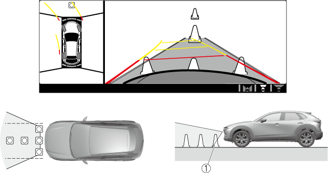
-
Target object
-
In the top view screen, the areas in black at the front and rear of the vehicle image and the seams where each of the camera images merge are blind spots.
-
Because images displayed in the top view screen are processed from each camera, the top view screen may display in the following ways.
-
If an image containing an object with a conspicuous colour is picked up by any of the cameras, the screen area for each camera may be affected and it may display in that colour.
-
Obstructions displayed in the front view may not display on the top view screen.
-
If the position or angle of each camera changes due to tilting of the vehicle, the image may appear distorted.
-
Lines on the road may appear distorted at the seams where each of the camera images merge.
-
The screen area for each camera may appear bright/dark depending on the illumination level around any of the cameras.
-


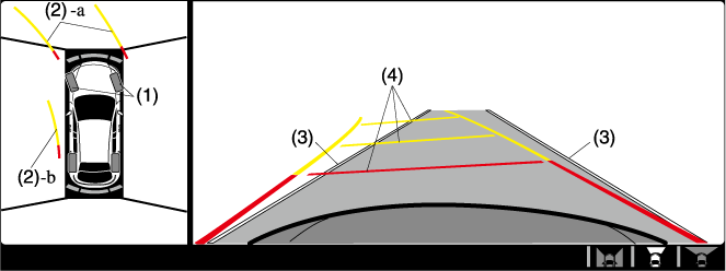
Viewing the screen
|
Display/Icon |
Content |
|
|---|---|---|
|
(1) |
Tyre icon |
Indicates the tyre direction. Moves in conjunction with the steering wheel operation. |
|
(2) |
Projected vehicle path lines (yellow & red) |
Indicates the approximate projected path of the vehicle. Moves in conjunction with the steering wheel operation. a) Indicates the path where the edge of the front bumper is expected to travel. b) Indicates the path where the inner side of the vehicle is expected to travel. |
|
(3) |
Extended vehicle width lines (blue) |
Indicates the approximate width of the vehicle. |
|
(4) |
Projected vehicle path distance guide lines (yellow & red) |
Indicates the distance (from front end of bumper) in front of the vehicle.
|
The parking sensor detection range has limitations. For example, obstructions closing in from the side and objects short in height may not be detected. Always confirm the safety around the vehicle visually when driving.
For details, refer to the parking sensor obstruction detection indication and warning sound.
Refer to Parking Sensor System (Search).
The setting can be changed so that the projected vehicle path lines are not displayed.
Refer to the Settings section in the Mazda Connect Owner's Manual.
How to use the projected vehicle path line function
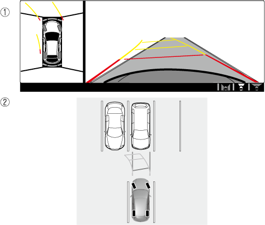
-
(Screen display)
-
(Actual condition)
Make sure that there are no obstructions within the projected vehicle path lines.
Drive the vehicle forward while turning the steering wheel so that no obstructions come within the projected vehicle path lines.